8
MOTOR CONTROL
✓
NOTE!
The setting with too short ramp time may cause overcurrent in the output (F070), undervoltage (F021)
or overvoltage (F022) of the DC link.
P100 - Acceleration Time
P101 - Deceleration Time
P102 - Acceleration Time 2nd Ramp
P103 - Deceleration Time 2nd Ramp
P106 - Emer. R. Acceleration Time
P107 - Emer. R. Time Deceleration
Range: 0.1 to 999.9 s
Description:
Acceleration and deceleration times according to the active ramp (standard, 2
nd
ramp or emergency ramp).
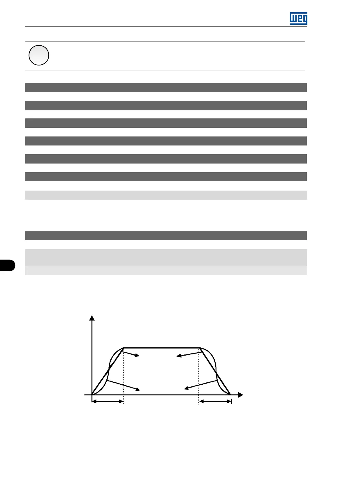
P104 - Ramp S
Range: 0 = Inactive
1 = Active
Properties: cfg
Description:
This parameter allows the inverter acceleration and deceleration ramps to have a non-linear profile, similar to an
”S”, aiming at reducing the mechanical shocks on the load, as shown in Figure 8.1 on page 8-2.
t(s)
Output
frequency
Linear ramp
Ramp S
Acceleration time
(P100/P102)
Deceleration time
(P101/P103)
Figure 8.1: S or Linear ramp
8-2 | Micro Mini Drives