6 | CFW501
General Information
English
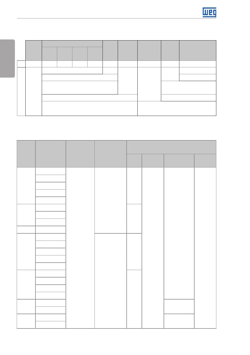
2.3 NOMENCLATURE
Table 2.1: Nomenclature of the inverters CFW501
Product
and
Series
Identification of the Model
Brake
(*)
Protection
Rate
(*)
Conducted
Emission
Level
(*)
Hardware
Version
Special Software
Version
Frame
Rating
Current
No of
Phases
Rating
Voltage
Ex.: CFW501 A 02P6 T 4 NB 20 C2 --- --
Available options
CFW501
See table 2.2. Blank = standard
NB = without dynamic braking Sx = special software
DB = with dynamic braking
Blank = CFW500-CRS485
plug-in module
20 = IP20 H00 = without plug-in
N1 = cabinet Nema1 (type 1 as per UL) (protection rate
according to standard IEC IP20)
C2 or C3 = for inverters with internal filter.
In order to comply with IEC 61800-3, refer to
table B.3 and check the operation conditions.
(*) The available options for each model are in table 2.2.
Table 2.2: Available options for each field of the nomenclature according to the rating current and
voltage of the inverter
Frame
Output Rating
Current
N° of Phases Rating Voltage
Available Options for the Remaining
Identification Codes of the Inverters
Brake
Protection
Rate
Conducted
Emission Level
Hardware
Version
A
01P6 = 1.6 A
T = three-
phase power
supply
2 = 200...240 V
NB
20 or N1
C3
Blank or
H00
02P6 = 2.6 A
04P3 = 4.3 A
07P0 = 7.0 A
09P6 = 9.6 A
B
07P3 = 7.3 A
DB
10P0 = 10 A
16P0 = 16 A
C 24P0 = 24 A
A
01P0 = 1.0 A
4 = 380...480 V
NB
01P6 = 1.6 A
02P6 = 2.6 A
04P3 = 4.3 A
06P1 = 6.1 A
B
02P6 = 2.6 A
DB
04P3 = 4.3 A
06P5 = 6.5 A
10P0 = 10 A
C
14P0 = 14 A
C2
16P0 = 16 A
D
24P0 = 24 A
C3
31P0 = 31 A