16 | CFW501
Installation and Connection
English
When using shielded cables to install the motor:
Follow the safety recommendations of IEC 60034-25.
Use the low impedance connection for high frequencies to connect the cable shield
to the grounding. Use parts supplied with the inverter.
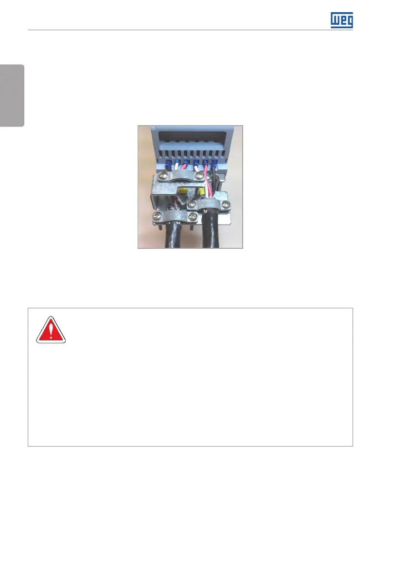
The accessory “CFW500-KPCSx power and control cable shielding kit” can be mounted
in the lower part of the cabinet. Figure 3.3 shows a detailed example of the connection
of the power supply and the motor cable shield to the accessory CFW500-KPCSA.
Besides, this accessory allows the connection of the control cable shield.
Figure 3.3: Details of the connection of the power supply and the motor cable shield to the accessory
CFW500-KPCSA
3.2.4 Grounding Connections
DANGER!
The inverter must be connected to a protection grounding (PE).
Use grounding wiring with a gauge at least equal to that indicated in table B.1.
The maximum tightening torque of the grounding connections is of 1.7 N.m
(15 lbf.in).
Connect the grounding points of the inverter to a specific grounding
rod, or specific grounding point or to the general grounding point
(resistance ≤ 10 Ω).
The neuter conductor that powers up the inverter must be solidly grounded;
however, this conductor must not be used to ground the inverter.
Do not share the grounding wiring with other equipment that operate
with high currents (e.g. high power motors, soldering machines, etc.).