CFW501 | 17
Installation and Connection
English
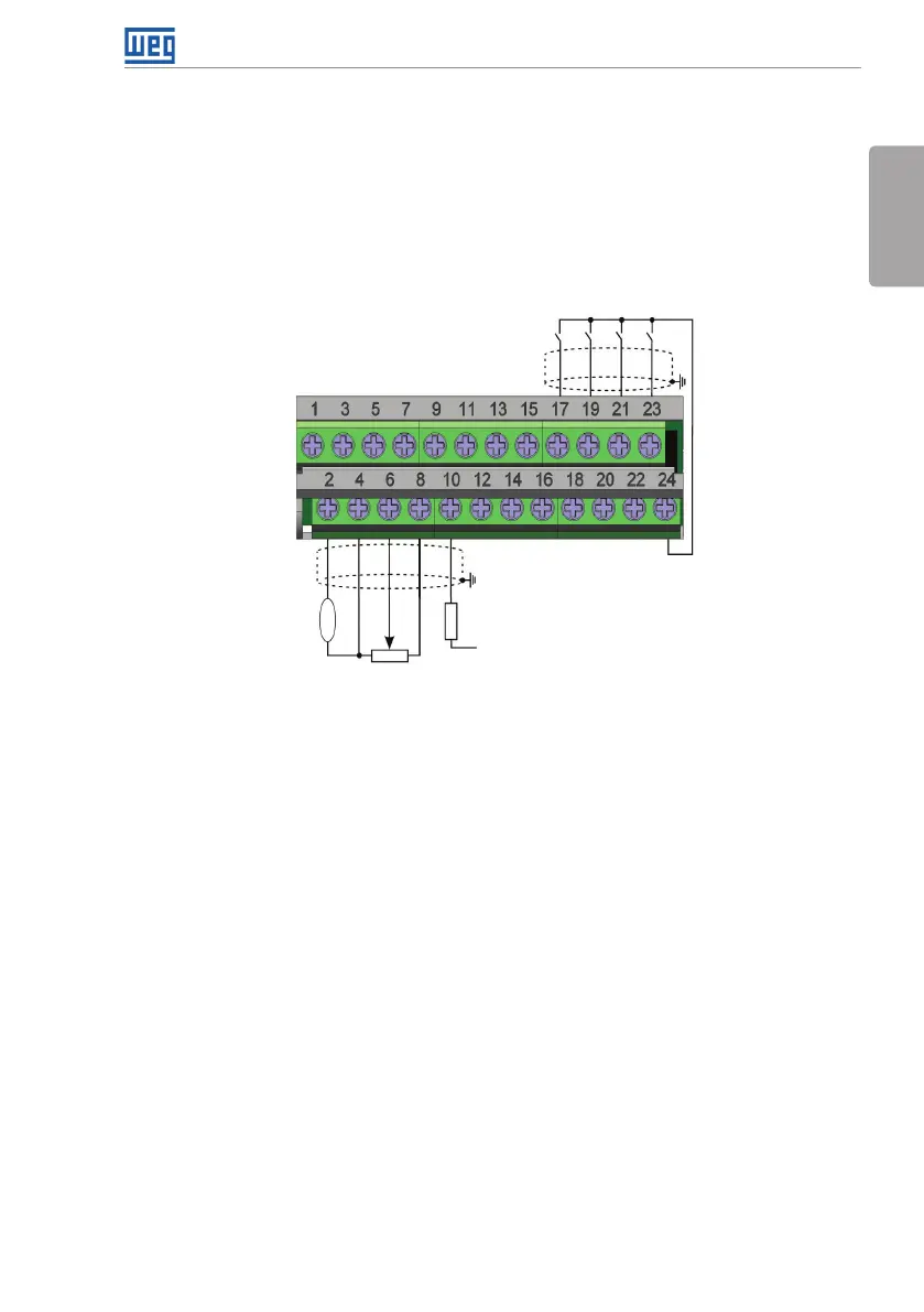
3.2.5 Control Connections
The control connections (analog input/output, digital input/output and interface RS485)
must be performed according to the specification of the connector of the plug-in module
connected to the CFW501. Refer to the guide of the plug-in module in the package of the
product or in the CD manual of the product. The typical functions and connections for
the CFW500-CRS485 plug-in module are shown in figure 3.4. For further details about
the specifications of the connector signals, refer to chapter 8 - Technical Specifications.
AI1
AO1
GND
+10 V
DO2-TR
R
rpm
GND
RS485 - B
RS485 - B2
+24 V
+24 V
DO1-RL -NO
DO3-RL -NO
DO1-RL -C
DO3-RL -C
DO1-RL -NC
DO3-RL -NC
NC
DI1
DI2
DI3
DI4
RS485 - A
RS485 - A2
≥5 kΩ
GND
AI2
Figure 3.4 (a): Signals of the connector of the CFW500-CRS485 plug-in module