CFW501 | 137
Appendix B / Anexo B
Appendix B
Anexo B
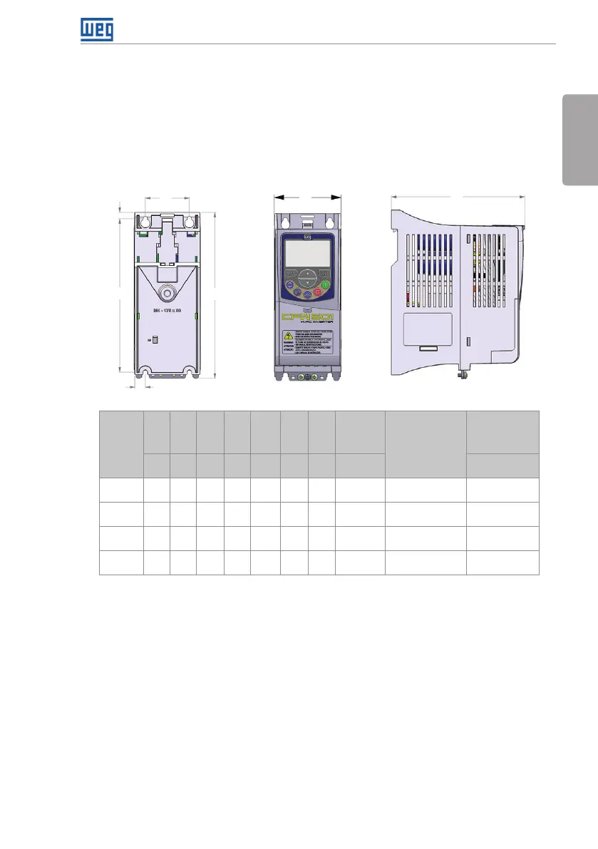
Size A, B and C – Standard Inverter
Mecánica A, B y C – Convertidor Estándar
Mecânica A, B e C – Inversor Padrão
VIIES OF THE
MOUNTING BASE
VISTA DE LA BASE
DE FIJACIÓN
VISTA DA BASE DE
FIXAÇÃO
FRONT VIEW
VISTA FRONTAL
SIDE VIEW
VISTA L ATERAL
D
A
C
P
B
H
L
Frame
Mecánica
Mecânica
A B C D H L P
Weight
Peso
Peso
Mounting Bolt
Tornillo de Fijación
Parafuso para
Fixação
Recommended
Torque
Torque
recomendado
mm
(in)
mm
(in)
mm
(in)
mm
(in)
mm
(in)
mm
(in)
mm
(in)
kg
(lb)
N.m (lbf.in)
A
50
(1.97)
175
(6.89)
11.9
(0.47)
7.2
(0.28)
189
(7.44)
75
(2.95)
150
(5.91)
0.8 (1.76)
(1)
M4 2 (17.7)
B
75
(2.95)
185
(7.3 0 )
11.8
(0.46)
7.3
(0.29)
199
(7.8 3)
100
(3.94)
160
(6.30)
1.2 (2.65)
(1)
M4 2 (17.7)
C
100
(3.94)
195
(7.70)
16.7
(0.66)
5.8
(0.23)
210
(8.27)
135
(5.31)
165
(6.50)
2 (4.4) M5 3 (26.5)
D
125
(4.92)
290
(11.41)
27. 5
(1.08)
10.2
(0.40)
306.6
(12.1)
180
(7.08)
166.5
(6.55)
4.3 (0.16) M6 4.5 (39.82)
Dimension tolerance: ±1.0 mm (±0.039 in)
(1) This value refers to the heaviest weight of the frame size.
Tolerancia de las cotas: ±1.0 mm (±0.039 in)
(1) Este valor se refiere al mayor peso para el mismo tamaño.
Tolerância das cotas: ±1.0 mm (±0.039 in)
(1) Este valor refere-se ao maior peso da mecânica.
Figure B.1: Inverter dimensions for mechanical installation
Figura B.1: Dimensiones del convertidor de frecuencia para la instalación mecánica
Figura B.1: Dimensões do inversor para instalação mecânica