www.wegener.com 800092-01 Rev. A 5
Unity 552 User’s Manual
Technical
Specifica
-
tions
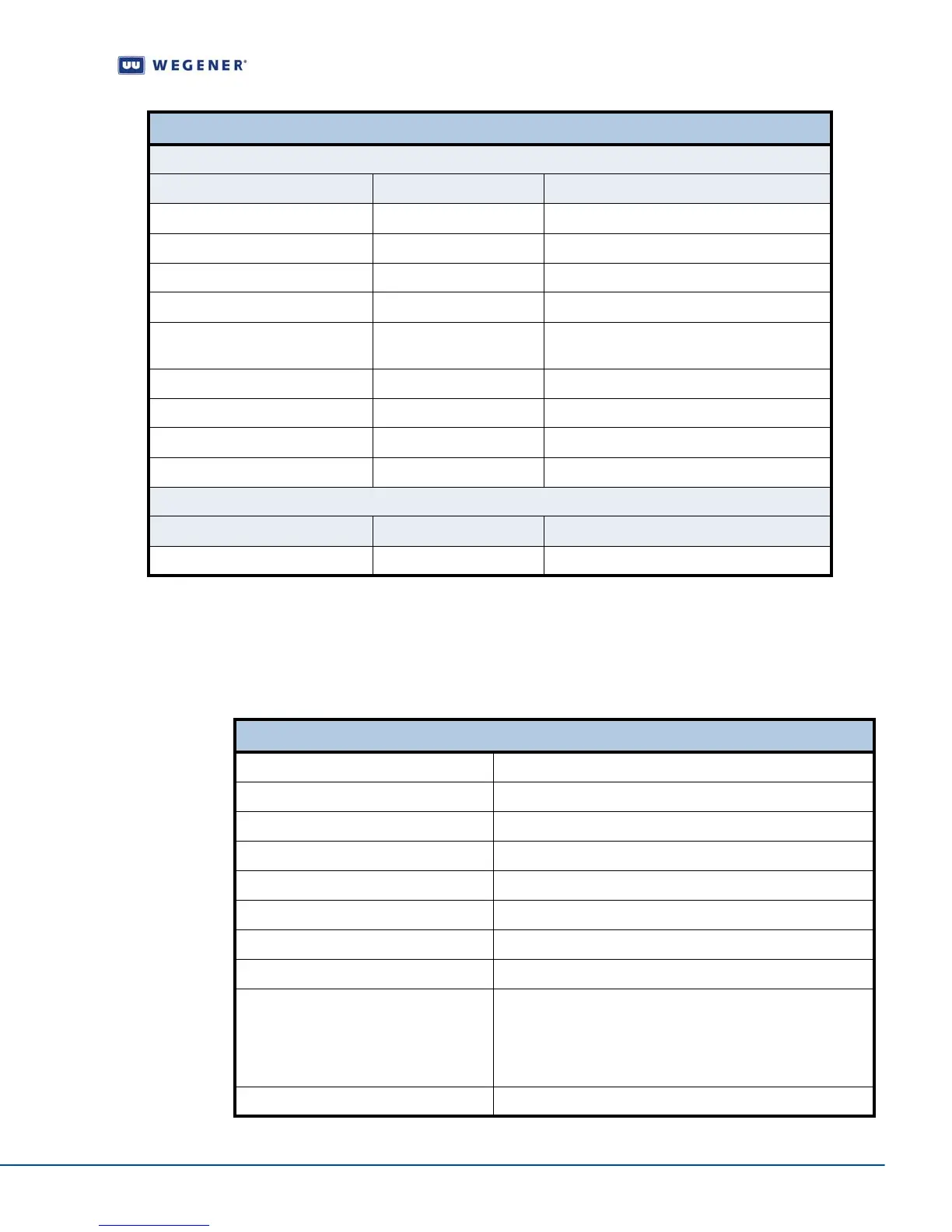
The following tables detail the technical specifications for the iPump 562.
RF Characteristics
Table 1.3: iPump 562 RF Characteristics
Contact Closure GPIO DB-9 Female
Connector Pin Input/Output Description
1 Alarm Common
2 Alarm Normally Open
3 Contact Closure Common
4 No Connection
5 Input Contact Closure GPIO Input
(Factory use only)
6 Alarm Normally Closed
7 Contact Closure Normally Closed
8 Contact Closure Normally Open
9 NA Ground
Power DC IN 12 V 5 A
Connector Input/Output Description
Standard IEC Input 115 or 230 V AC
External Input/Output Interfaces
RF Characteristics
RF Input Connector Type F
Input Frequency Range 950 - 2150 MHz
Input Level Range -25 to -65dBm
Maximum Aggregate Input Power -8 dBm at max input signal
Input Impedance 75 ohms
Input VSWR < 2.5:1
Input Noise Figure 8 dB MAX at minimum input level
L.O. Leakage at Input < -55 dBm
Demodulator
DVB-S QPSK
DVB-S2 QPSK
DVB-S2, 8PSK
FEC Rate 1/2, 2/3, 3/4, 5/6, or 7/8 (1.0 to 45 MBaud) ½, 2/3,
¾, 4/5, 5/6, 7/8, 9/10 (2 to 30 MBaud) 2/3, ¾, 5/6, 8/9, 9/10
(3 to 30 MBaud) Convert Symbol Rate Fs to Transport Rate
Ft by: (2R*Fs)*(188/204)=Ft, where 'R' is inner FEC code
ratio, either R=1/2, 2/3, 3/4, 5/6, or 7/8.
Max Symbol-rate S2 = 30 Msps; S1 = 45 Mbps