Do you have a question about the West Control Solutions Pro-EC44 and is the answer not in the manual?
Details the warranty terms for product defects in material and workmanship.
Outlines limitations on liability for damages and conditions for warranty claims.
Guidelines for mounting the controller in a panel, including cut-out dimensions.
Instructions for cleaning the front panel of the instrument.
Details available plug-in modules to expand controller capabilities.
Information about the data recorder memory and Real Time Clock components.
Details on how to enable the profiler feature, potentially via a licence code.
Recommendations to reduce the possibility of Electromagnetic Compatibility issues.
Guidelines for isolating and protecting input and output wiring.
Methods for suppressing electrical noise at its source to improve signal integrity.
Details on terminal connections for various modules, power, and inputs.
Step-by-step instructions for powering up the instrument for the first time.
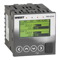
Identifies the main components and features of the instrument's front panel.
Describes messages related to invalid or unknown plug-in modules and troubleshooting steps.
Explains how sensor break conditions are detected and their effect on control outputs.
Details what happens if calibration data is lost and how to perform a base calibration.
Key questions to consider before configuring the controller for an application.
Describes the primary operating mode, screen navigation, and value adjustment.
Guides basic application setup, accessible from Main Menu or at first power-up.
Allows access to a lock-code protected sub-set of configuration parameters.
Provides access to sub-menus for detailed instrument configuration and settings.
Explains how to adjust displayed values relative to actual measured values.
Method for applying separate offsets at two points to eliminate zero and span errors.
Enables linearization of non-linear signals using up to 15 breakpoints.
Describes how digital inputs are driven by voltage signals or contacts.
Four "soft" digital inputs available, used to select functions via Boolean logic.
Lists the possible functions that can be assigned to each digital input.
Explains how the master and slave loops operate when coupled.
Steps for tuning the slave and master loops, including automatic pre-tuning.
Specific wiring advice for controlling valve motors, including interlocking relays.
Setting upper and lower limits to control valve movement.
Options for setting the main and alternate setpoints for loop 1.
Options for setting the main and alternate setpoints for loop 2.
General configuration settings applicable to all profiles.
Explains standard segment types like ramps, dwells, and steps.
Defines actions taken when power or signal is lost during profile execution.
Actions taken after a profile normally finishes, based on segment end type.
How to upload or download settings and data using a USB memory stick.
Explains the required folder structure and file naming conventions for USB operations.
Lists the selectable values that can be recorded, including process variables and alarm statuses.
Options for starting, stopping, and deleting recordings, and viewing status information.
How to enter PID tuning terms and use gain scheduling for optimal control.
Using Pre-Tune, Self-Tune, or Auto Pre-Tune to automatically optimize tuning terms.
Step-by-step procedures for manual tuning of PID control loops.
Outlines supported protocols like Modbus RTU and Modbus TCP.
Parameters for configuring RS485 communications, including data rate and parity.
Parameters for configuring Ethernet communications for Modbus TCP.
Describes the currently selected setpoint used by the controller.
Sub-menu for adjusting alarm parameters like types, values, and hysteresis.
Splitting a process into cascaded loops for difficult-to-control applications.
Sub-menu for adjusting parameters related to process control.
The difference between process variable and actual setpoint.
Input driven by voltage or contact, used for various instrument states.
Switches PID values automatically based on setpoint or process values for optimal control.
Overview of menus, button bars, and parameter screens in the software.
Interactive simulation for testing instrument settings before deployment.
Steps to establish communication between PC and instrument via various ports.
General specifications for process inputs, including sample rate and resolution.
Performance specifications for thermocouple inputs, including types and ranges.
Specifications for DC linear input types and ranges.
Details the performance characteristics of various output module types.
Specifications for supported communication methods like RS485 and Ethernet.
Defines control types, feedback, tuning, and PID parameters.
Information on the number, types, and configuration of alarms.
| Category | Temperature Controller |
|---|---|
| Type | Pro-EC44 |
| Output 1 | Relay |
| Output 2 | Relay |
| Control Mode | PID, On/Off |
| Input Type | Thermocouple, RTD |
| Display Type | Dual 4-digit LED |
| Operating Temperature | 0 to 50°C |
| Supply Voltage | 100-240 VAC |
| Output Type | Relay |
| Power Supply | 100-240 VAC |
| Protection Rating | IP65 |