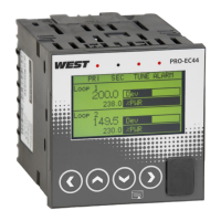
Pro-EC44 2-Loop Graphical Profile Controller & Recorder
Pro-EC44 Product Manual - 59540-2 September 2014 Page 6
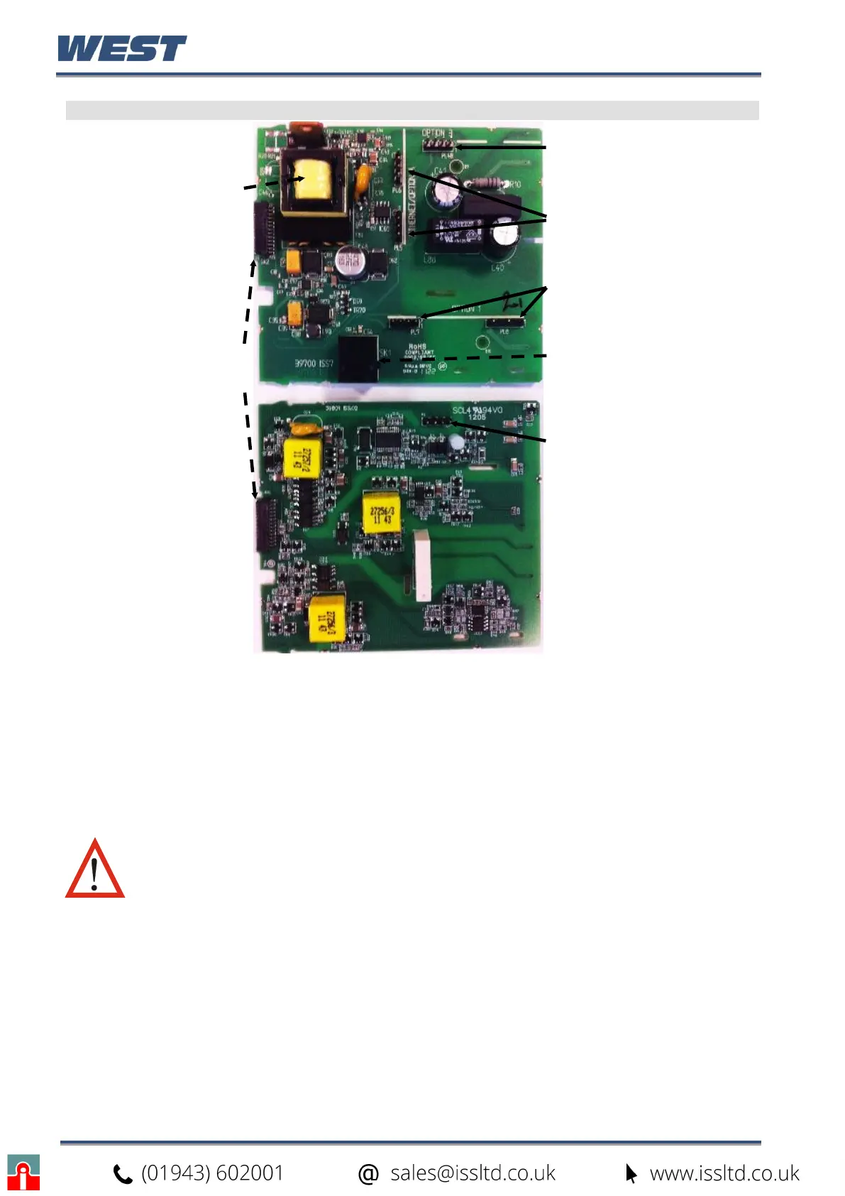
Main Board Connectors
BOARD
Code
100-240V (Yellow)
24-48V(Blue)
Display Board
Connections
1st UNIVERSAL
INPUT / BASE
OPTION 1 BOARD
Module Slot 3
Connector PL4B
Module Slot A
Connectors PL5, & PL6
Module Slot 1
Connectors PL7 & PL8
PC Configurator
Socket SK1
Module Slot 2
Connector PL4A
Figure 4. Main board connectors
This product is designed to allow the user to reconfigure some hardware options in the field
by changing the plug-in modules in slots 1, 2, 3, & A located on the power supply and 1
st
universal input boards. The main boards (display/CPU, power supply, inputs 1 & 2 and digital
input/USB) are factory fitted, but may be removed while reconfiguring the plug-in modules.
Take care when re-fitting these boards. Observe the power supply board transformer colour,
and case labelling to check the supply voltage, otherwise irreparable damage may occur.
CAUTION: Replacement of boards must be carried out by a technically
competent technician. If the Power Supply board does not match the
labelling, users may apply incorrect voltage resulting in irreparable
damage.