Pro-EC44 2-Loop Graphical Profile Controller & Recorder
Pro-EC44 Product Manual - 59540-2 September 2014 Page 237
A communications settings screen is shown whenever the user attempts to connect to the
instrument from the software. If the settings are not in-line with the information below, the
software may not be able to communicate with the instrument.
Connection from PC to Bottom Configuration Socket
When using the built-in configuration socket, set the communications parameters as shown
here and in the following table.
Device connector = Configuration Socket
PC connector = the PC Serial Com port number you are connected to
Start and Stop bits = 1
Data bits = 8.
Parity, Bit Rate & Address = must match settings in the table below
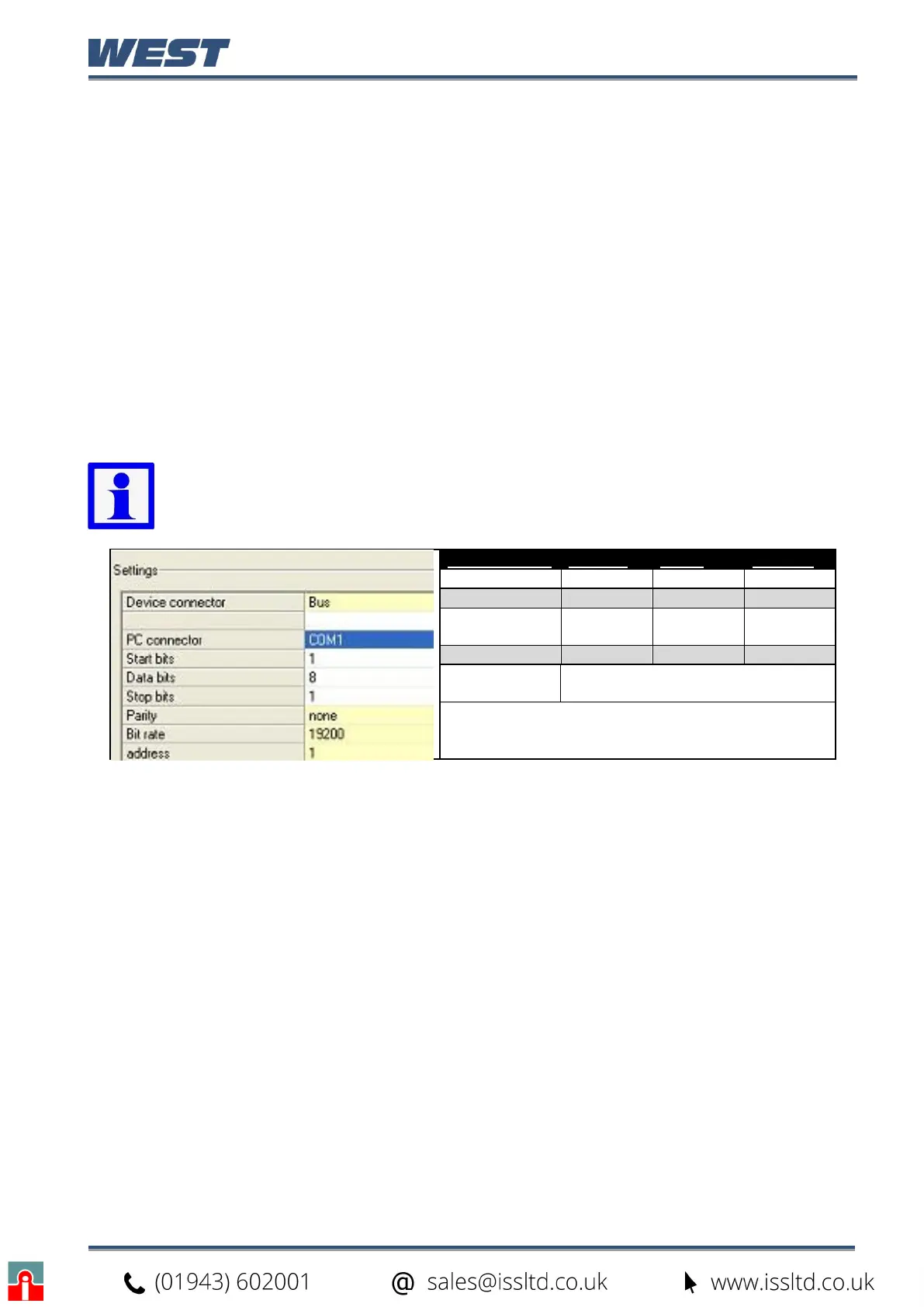
Connection from PC to Rear RS485 Communications Option
When using the optional RS485 communications, set the parameters as shown here.
Device connector = Bus
PC connector = the PC Serial Com port number you are connected to
Start and Stop bits = 1
Data bits = 8
Parity, Bit Rate & Address = must match the settings in the instruments own
Communication Configuration menu.
Note: When uploading or downloading via the bottom mounted configuration
port, the required software communication settings depend on the module fitted
in slot A. See the table below.
Slot A Module Bit Rate Parity Address
Slot A Empty 19200 None 1
Digital Input 19200 None 1
Ethernet
Comms
9600 None 1
Auxiliary Input 4800 None 1
RS485
Comms
Must match the Communication
Configuration menu settings.