Pro-EC44 2-Loop Graphical Profile Controller & Recorder
Pro-EC44 Product Manual - 59540-2 September 2014 Page 198
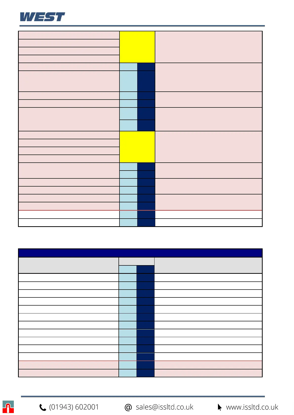
Profile Start Time (Byte 4 - High)
A/R
(Floating
point
number)
The time, in elapsed seconds, from the start
trigger before a profile will begin if Start Signal
=1 (After Delay) or seconds from midnight if
Start Signal =2 (Time of Day)
Is zero if Start Signal =0 (No Delay)
Profile Start Time (Byte 3)
Profile Start Time (Byte 2)
Profile Start Time (Byte 1 - Low)
Profile Start Day High Byte
0 0
1 = Monday, 2 = Tuesday, 3 = Wednesday, 4
= Thursday, 5 = Friday, 6 = Saturday, 7 =
Sunday, 8 = Monday to Friday, 9 = Monday to
Saturday, 10 = Saturday And Sunday, 11= All
Week
Profile Start Day Low Byte
A/R A/R
Profile Starting Setpoint High
0 0
0 = Current Setpoint, 1 = Current Process
Value
Profile Starting Setpoint Low
A/R A/R
Profile Recovery High Byte
0 0
0 = Control to off, 1 = Restart profile, 2 =
Maintain last profile setpoint, 3 = Use
controller setpoint, 4 = Continue profile from
where it was when power failed
Profile Recovery Low Byte
A/R A/R
Profile Recovery Time (Byte 4 - high)
A/R
(Floating
point
number)
The Profile Recovery Time (before the
recovery action will be used after power/signal
returns) in elapsed seconds.
Is zero if no recorder (RTC) fitted - function
not possible
Profile Recovery Time (Byte 3)
Profile Recovery Time (Byte 2)
Profile Recovery Time (Byte 1 - Low)
Profile Abort action High Byte
0 0
0 = Control to off, 1 = Maintain last profile
setpoint, 2 = Use controller setpoint
Profile Abort Action Low Byte
A/R A/R
Profile Cycles High Byte
A/R A/R
1 to 9999 or 10,000 for “Infinite”
Profile Cycles Low Byte
A/R A/R
Profile Number of Loops High Byte
0 0
The number of loops controlled by the profile:
1 or 2
Profile Number of Loops Low Byte
A/R A/R
CRC High Byte
A/R A/R
CRC Low Byte
A/R A/R
Read a Segment
Read A Segment - Request (to instrument)
Field Name
Data
Comments
Dec Hex
Unit Address
A/R A/R
The ID address of the instrument
Function Code
23 17
Requires the multi read/write function
Read Start Address High Byte
32 20
Read Start Address Low Byte
6 6
Read Quantity Of Registers High Byte
0 0
Read Quantity Of Registers Low Byte
17 11
Write Start Address High Byte
22 16
Write Start Address Low Byte
6 6
Write Quantity Of Registers High Byte
0 0
Write Quantity Of Registers Low Byte
3 3
Byte Count
6 6
Command Code High Byte
82 52
Command Code Low Byte
83 53