Pro-EC44 2-Loop Graphical Profile Controller & Recorder
Pro-EC44 Product Manual - 59540-2 September 2014 Page 190
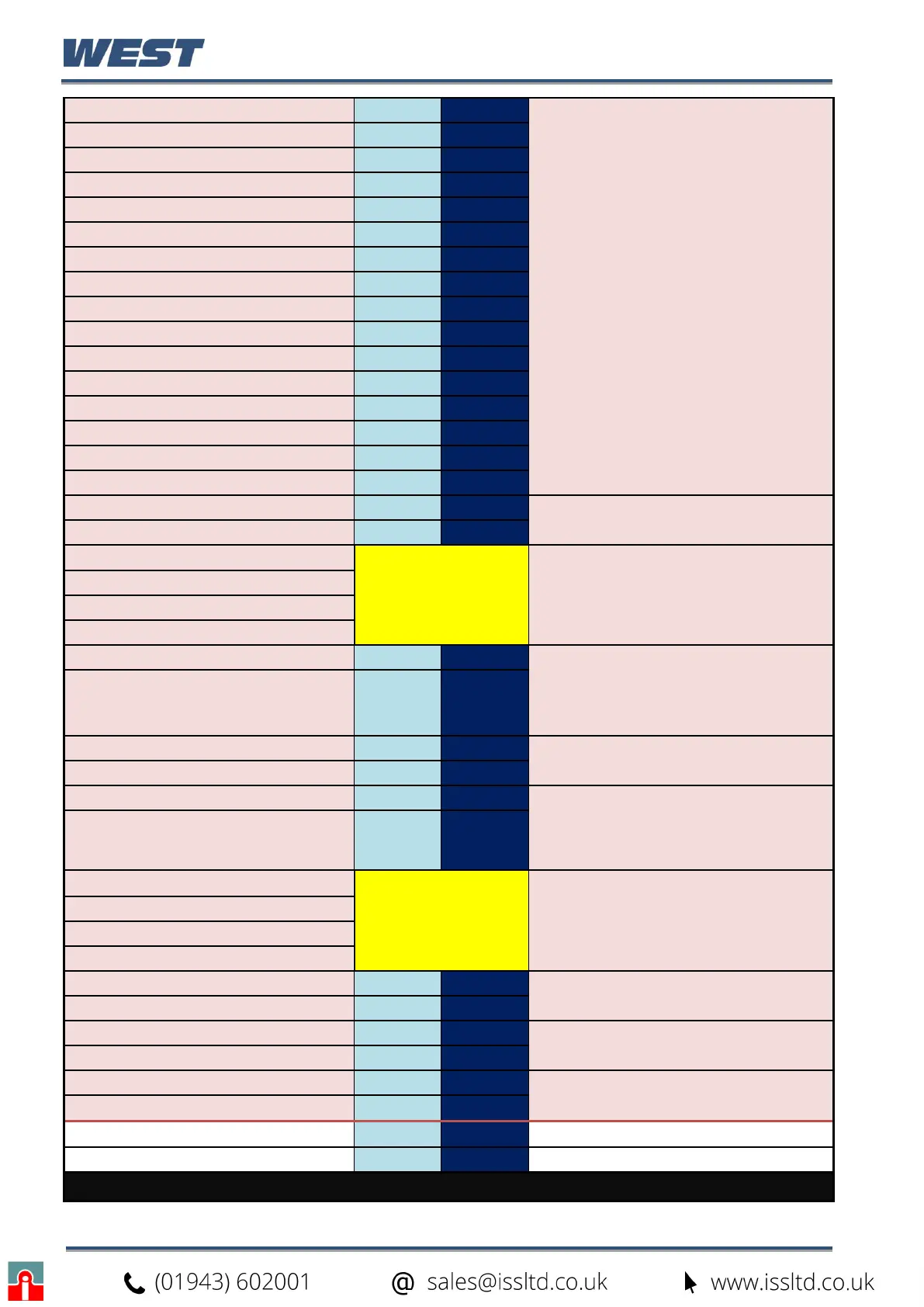
Profile Name Character 1
A/R A/R
The ASCII codes equivalent to each of the
16 characters of the profile name, e.g.:
A = 65dec / 0x41, B = 66dec / 0x42 etc.
a = 97dec / 0x61, b = 98dec / 0x62 etc.
Valid characters are 0 to 9, a to z, A to Z,
plus ß ö ( ) - and _.
Note: Only valid characters from the
instruments supported character set
should be used
The space character (32dec / 0x20hex) is
used to fill any unused characters at the
end of the name.
Profile Name Character 2
A/R A/R
Profile Name Character 3
A/R A/R
Profile Name Character 4
A/R A/R
Profile Name Character 5
A/R A/R
Profile Name Character 6
A/R A/R
Profile Name Character 7
A/R A/R
Profile Name Character 8
A/R A/R
Profile Name Character 9
A/R A/R
Profile Name Character 10
A/R A/R
Profile Name Character 11
A/R A/R
Profile Name Character 12
A/R A/R
Profile Name Character 13
A/R A/R
Profile Name Character 14
A/R A/R
Profile Name Character 15
A/R A/R
Profile Name Character 16
A/R A/R
Profile Start Signal High Byte
0 0
0 = No delay, 1 = After delay, 2 = At
Time/day *2 only if recorder (RTC) fitted
Profile Start Signal Low Byte
A/R A/R
Profile Start Time (Byte 4 - High)
A/R
(Floating point
number)
The time, in elapsed seconds from the start
trigger, before a profile will begin if Start
Signal =1 (After Delay) or seconds from
midnight if Start Signal =2 (Time of Day)
Use zero if Start Signal =0 (No Delay)
Profile Start Time (Byte 3)
Profile Start Time (Byte 2)
Profile Start Time (Byte 1 - Low)
Profile Start Day High Byte
0 0
1 = Monday, 2 = Tuesday, 3 = Wednesday,
4 = Thursday, 5 = Friday, 6 = Saturday, 7 =
Sunday, 8 = Monday to Friday, 9 = Monday
to Saturday, 10 = Saturday And Sunday,
11= All Week. Use 1 if no recorder fitted.
Profile Start Day Low Byte
A/R A/R
Profile Starting Setpoint High
0 0
0 = Current Setpoint, 1 = Current Process
Variable Value
Profile Starting Setpoint Low
A/R A/R
Profile Recovery High Byte
0 0
0 = Control to off, 1 = Restart profile, 2 =
Maintain last profile setpoint, 3 = Use
controller setpoint, 4 = Continue profile
from where it was when power failed
Profile Recovery Low Byte
A/R A/R
Profile Recovery Time (Byte 4 - high)
A/R
(Floating point
number)
The Profile Recovery Time (before the
recovery action will be used after
power/signal returns).
Entered as elapsed seconds.
Use zero if no recorder fitted.
Profile Recovery Time (Byte 3)
Profile Recovery Time (Byte 2)
Profile Recovery Time (Byte 1 - Low)
Profile Abort action High Byte
0 0
0 = Control to off, 1 = Maintain last profile
setpoint, 2 = Use controller setpoint
Profile Abort Action Low Byte
A/R A/R
Profile Cycles High Byte
A/R A/R
1 to 9999 or 10,000 for “Infinite”
Profile Cycles Low Byte
A/R A/R
Profile Number of Loops High Byte
0 0
The number of loops to be controlled by the
profile: 1 or 2
Profile Number of Loops Low Byte
A/R A/R
CRC High Byte
A/R A/R
CRC Low Byte
A/R A/R
The instrument replies to this message with an Edit Response Message.