LOW
VOLTAGE
-
ROTATING
FIELD
AUXILIARY
WINDINGS
TESTS
A
WARNING:
Some
of
the
following
tests
require
the
generator
to
be
running,
make
certain
the
front
pulley
cover
and
timing
belt
covetS
are
in
place.
ROTATING
FIELD/AUXILIARY
WINDINGS
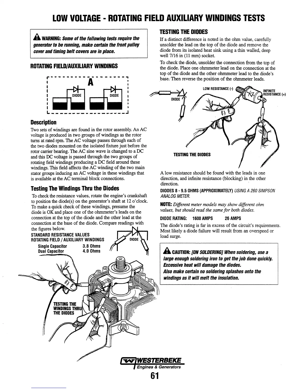
r------------------,
• A . :
I~~I
f..-Q~1
L
_.
__
.
_____
...
_____
.
____
..:1
Description
Two
sets of windings are found
in
the rotor
assembly.
An AC
voltage
is
produced
in
two groups
of
windings
as
the
rotor
turns at
rated
rpm.
The AC voltage passes through
each
of
the
two
diodes
mounted on the isolated fixture just before the
rotor carrier bearing. The AC sine wave
is
changed
to
a DC
and
this
DC
voltage is passed through the two groups of
rotating
field
windings producing a DC
field
around these
windings.
This
field
affects the AC winding
of
the
two
main
stator
groups
inducing an AC voltage in these windings that
is
available
at
the
AC
terminal block connections.
Testing
The
Windings
Thru
the
Diodes
To
check
the
resistance values, rotate the engine's crankshaft
to
position
the
diode(s) on the generator's shaft
at
12
o'clock.
To
make
a quick check
of
these windings, presume the
diode
is
OK
and place one
of
the ohmmeter's leads
on
the
connection
at
the
top
of
the diode and the other lead
at
the
connection
at
the base
of
the diode. Compare readings with
the figures below.
STANDARD
RESISTANCE
VALUES
ROTATING
FIELD
I
AUXILIARY
WINDINGS
Single
CapaCitor
3.8
Ohms
Dual
Capacitor
4.0
Ohms
TESTING
THE
DIODES
If
a distinct difference
is
noted
in
the ohm value, carefully
unsolder the lead
on
the
top
of
the diode and remove
the
diode from its isolated heat sink using a thin walled, deep
well
7/16
in
(11
mm)
socket.
To
check the
diode,
unsolder the connection from the
top
of
the diode. Place one ohmmeter lead on the connection
at
the
top
of
the diode and the other ohmmeter lead
to
the diode's
base: Then reverse
the.
position
of
the ohmmeter leads.
TESTING
THE
DIODES
A low resistance should be found with the leads in one
direction, and infinite resistance (blocking)
in
the other
direction. .
DIODES
8 -
9.5
OHMS
(APPROXIMATELY)
USING
A
260
SIMPSON
ANALOG
METER.
NOTE:
Different meter models
may
show different
ohm
values. but should
read
the same for both
diodes.
DIODE
RATING:
1600
AMPS
26
AMPS
The diode's rating
is
far in excess
of
the circuit's requirements.
Most likely a diode failure will result from
an
overs peed
or
load surge.
A
CAUTION:
[ON
SOLDERING}
When
soldering,
use
a
large
enough
soldering
iron
to
get
the
job
done
quickly.
Excessive
heat
will
damage
the
diodes.
Also
make
certain
no
soldering
splashes
onto
the
windings
as
it
will
melt
the
insulation.
Engines & Generators
61