INTEGRAL
CONTROLLER
I
NO-LOAD
VOLTAGE
ADJUSTMENT
TESTING
THE
INTEGRAL
CONTROLLER
To
test the battery charger, put a multimeter between the
positive
(+) and negative (-) leads to
the
battery. It should
indicate 13.5V to
14V with the engine running.
If
only the
battery voltage is indicated, check that the battery charger
terminal connections are tight. With the unit running, test
between the
(+) and (-) terminals for·13.5V to 14V.
If
no
charge is indicated, replace the charger.
GROUND
.
CONNECTION
INTEGRAL
CONTROLLER
BRIDGE
'"
RECTIFIER
A 30 amp fuse protects the windings
from
a failure
of
the
bridge rectifier
or
integral controller (high amperage
or
a
short)
SINGLE
AND
DUAL
CAPACITOR
NO-LOAD
VOLTAGE
ADJUSTMENT
1.
Remove the louvered metal plate, at the back
of
the
generator, covering
t1>.e
AC terminal connections and
the capacitor(s).
2.
Start the generator and allow it to run for approximately
five minutes so the engine can warm up. Make sure the
generator
is
operating without any equipment drawing AC
current from the generator (that is, shut
off
all electrical
appliances). Make sure the engine's speed (Hertz) is
correct. Adjust the governor as needed to obtain the
correct engine speed before proceeding.
3. Refer to the AC
1ERMINAL
BOARD CONNECTIONS
DIAGRAM for the correct configuration then check
the
generator's no-load voltage by measuring the voltage
across the neutral lead and the hot lead with a voltmeter.
Make sure
you record this reading.
The
generator's no-
load voltage is 115 - 124 volts at
60.5 - 61.5 Hertz.
If
the
voltage output is higher or lower than specified, proceed.
4.
Shut
off
the generator. Make sure the correct Hertz lead
(60 Hertz #6,
or
50
Hertz #5) is plugged into the
capacitor(
s).
c
DUAL
CAPACITOR
50Hz
60Hz
117
118
A
WARNING:
Capacitors
must
be
discharged
before
handling
as
they
store
electricity
and
can
pack
a
poten-
tial/y
lethal
charge
even
when
disconnected
from
their
power
source.
NOTE:
Simply
cross
the
capacitor's
two
terminals
with
an
insu-
lated (plastic hmulle)
screwdriver.
This
will discharge any
excess
electricity.
A
WARNING:
Do
not
attempt
to
make
a
no-load
voltage
adjustment
while
the
generator
is
operating.
The
capaCitor
can
produce
a
400-500
volt
charge.
Touching
any
wiring
can
produce
a
severe
electrical
shock.
In
addition,
attempting
to
make
a
no-load
volt-
age
adjustment
while
the
generator
is
operating
could
cause
your
fingers
to
be
caught
in
the
generator's
rotor.
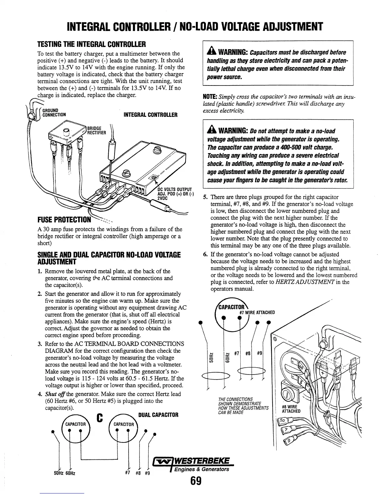
5. There are three plugs grouped for the right capacitor
terminal, #7, #8, and #9.
If
the generator's no-load voltage
is
low, then disconnect the lower numbered plug and
connect the plug with the next higher number.
If
the
generator's no-load voltage is high, then disconnect the
higher numbered plug and connect the plug with the next
lower number. Note that the plug presently connected to
this terminal may
be
anyone
of
the three plugs available.
6.
If
the generator's no-load voltage cannot be adjusted
because the voltage needs to
be increased and the highest
numbered plug is already connected to the right terminal,
or the voltage needs to be lowered and the lowest numbered
plug is connected, refer to
HERTZ ADJUSTMENT in the
operators manual.
N N
::I: ::I:
'" '"
It>
...
THE
CONNECTIONS
SHOWN
DEMONSTRATE
HOW
THESE
ADJUSTMENTS
CAN
BE
MADE