INTEGRAL
CONTROLLER
c
...
cc
cc
c
...
<.:I
z:
...
cc
c
B+
I~VOLlADJ.
POl.
+
-
GND
BLACK
YELLOW
INTEGRAL
CONTROLLER
GROUND
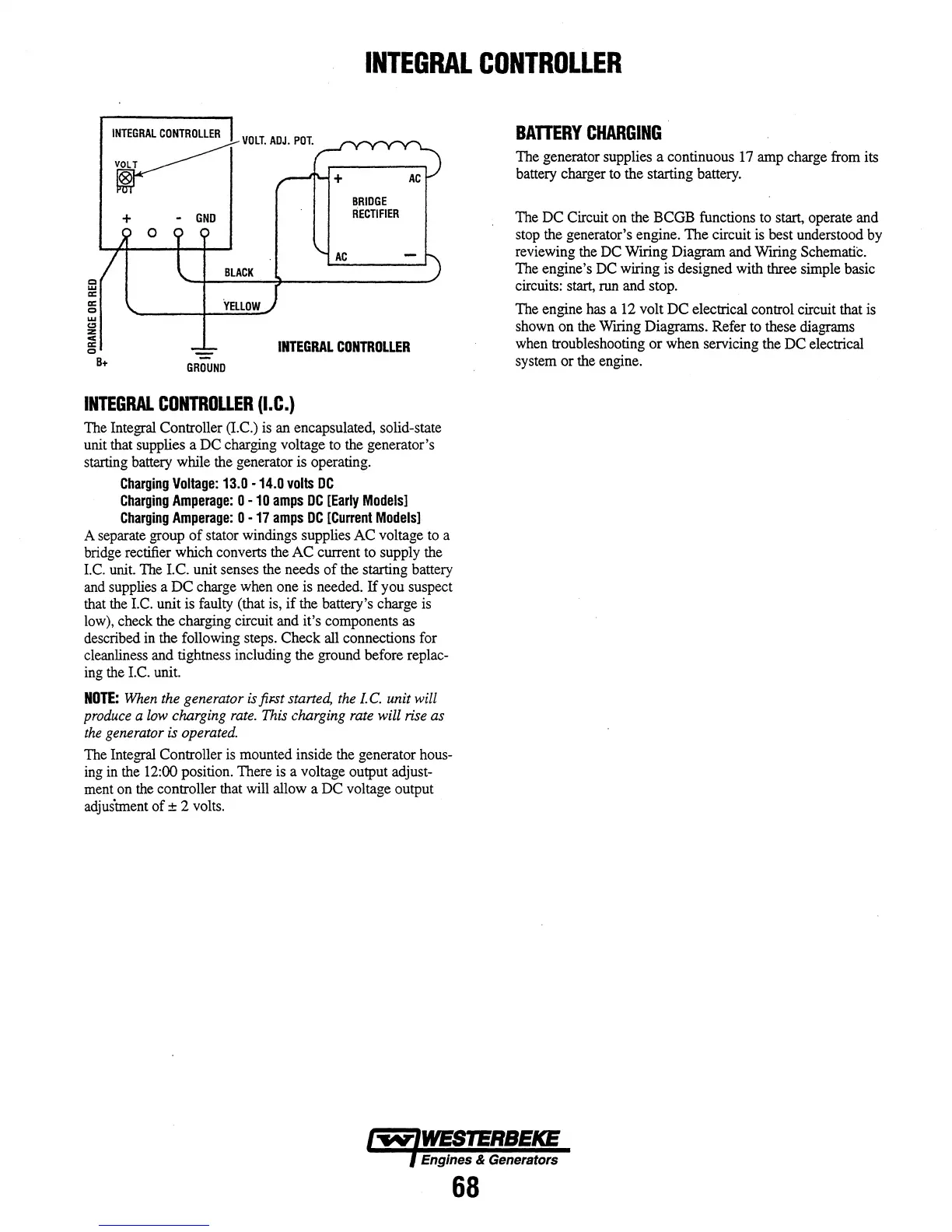
INTEGRAL
CONTROLLER
(I.C.)
The Integral Controller (I.e.)
is
an encapsulated, solid-state
unit that supplies a DC charging voltage to the generator's
starting battery while the generator is operating.
Charging
Voltage:
13.0
-14.0
volts
DC
Charging
Amperage:
0 -
10
amps
DC
[Early
Models]
Charging
Amperage:
0 -
17
amps
DC
[Current
Models]
A separate group
of
stator windings supplies AC voltage to a
bridge rectifier which converts the
AC
current to supply the
I.e. unit. The
I.e.
unit senses the needs
of
the starting battery
and supplies a
DC
charge when one is needed.
If
you suspect
that the I.C. unit is faulty (that is,
if
the battery's charge
is
low), check the charging circuit and it's components as
described
in
the following steps. Check all connections for
cleanliness and tightness including the ground before replac-
ing the
I.e.
unit.
NOTE:
When the generator
is
jiFSt
started, the
l.
C.
unit will
produce a low charging rate. This charging rate will rise as
the generator is operated.
The Integral Controller
is
mounted inside the generator hous-
ing
in
the 12:00 position. There
is
a voltage output adjust-
ment on the controller that will allow a DC voltage output
adjustment
of
± 2 volts.
BATTERY
CHARGING
The generator supplies a continuous 17 amp charge from its
battery charger to the starting battery.
The DC Circuit on the BCGB functions to start, operate and
stop the generator's engine. The circuit
is
best understood by
reviewing the DC
WIring Diagram and WIring Schematic.
The engine's DC wiring is designed with three simple basic
circuits: start, run and stop .
The engine has a 12 volt DC electrical control circuit that
is
shown on the WIring Diagrams. Refer to these diagrams
when troubleshooting
or
when servicing the DC electrical
system
or
the engine.
Engines & Generators
68