BATTERY
CHARGING
CIRCUIT
I
BRIDGE
RECTIFIER
TESTING
THE
BATTERY
CHARGING
CIRCUIT
NOTE:
The
battery charging circuit is totally separate from the
A
C output
of
the generator: The generator output affects the
circuits output, but
not
the reverse.
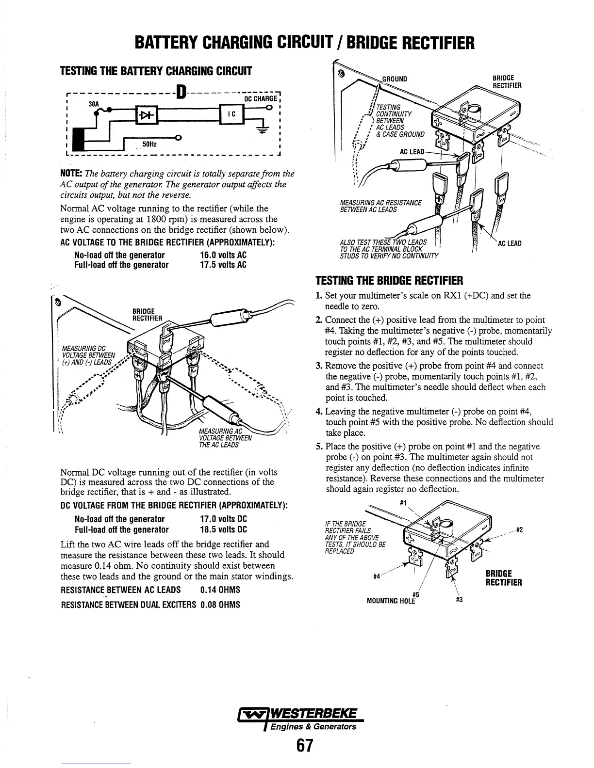
Normal AC voltage running to the rectifier (while the
engine is operating
at
1800 rpm) is measured across the
two AC connections
on
the bridge rectifier (shown below).
AC
VOLTAGE
TO
THE
BRIDGE
RECTIFIER
(APPROXIMATELY):
No-load
off
the
generator
Full-load
off
the
generator
MEASURING
DC
;
VOLTAGE
BETWEEN
.'
•
.
(+)
AND
(-)
LEADS
.,:.'
II
.'.~
,
...
:
.*-.,,;*.
I
;..
I
.'
••
II
..
.. ..
'1
.i:.
I'
Ii
~:p;.~
·1
"
'\
iii
l:
"
\ \
16.0
volts
AC
17.5
volts
AC
Normal DC voltage running out
of
the rectifier (in volts
DC) is measured across the two DC connections
of
the
bridge rectifier, that is + and - as illustrated.
DC
VOLTAGE
FROM
THE
BRIDGE
RECTIFIER
(APPROXIMATELY):
No-load
off
the
generator
Full-load
off
the
generator
17.0
volts
DC
18.5
volts
DC
Lift the two AC wire leads
off
the bridge rectifier and
measure the resistance between these two leads. It should
measure
0.14 ohm.
No
continuity should exist between
these two leads and the ground
or
the main stator windings.
RESISTANCE
BETWEEN
AC
LEADS
0.14
OHMS
RESISTANCE
BETWEEN
DUAL
EXCITERS
0.08
OHMS
ALSO
TEST
THESE
TWO
LEADS
TO
THE
AC
TERMINAL
BLOCK
STUDS
TO
VERIFY
NO
CONTINUllY
TESTING
THE
BRIDGE
RECTIFIER
1.
Set your multimeter's scale on RX1 (+DC) and set the
needle to zero.
2. Connect the (+) positive lead from the
mu~timeter
to
point
#4. Taking the multimeter's negative (-) probe, momentarily
touch points #1, #2, #3, and #5. The multimeter should
register no deflection for any
of
the points touched.
3. Remove the positive (+) probe from point #4 and connect
the negative (-) probe, momentarily touch points #1, #2,
and #3. The multimeter's needle should deflect when each
point
is
touched.
4. Leaving the negative multimeter (-) probe on point #4,
touch point #5 with the positive probe. No deflection should
take place.
S.
Place the positive (+) probe on point
#1
and the negative
probe (-) on point #3. The multimeter again should not
register any deflection (no deflection indicates infinite
resistance). Reverse these connections and the multimeter
snould again register no deflection.
/
#5
MOUNTING
HOLE'
#3
#2
BRIDGE
RECTIFIER
Engines & Generators
67