/
II
I
EXCITER
CIRCUIT
CAPACITOR{S)
TESTS
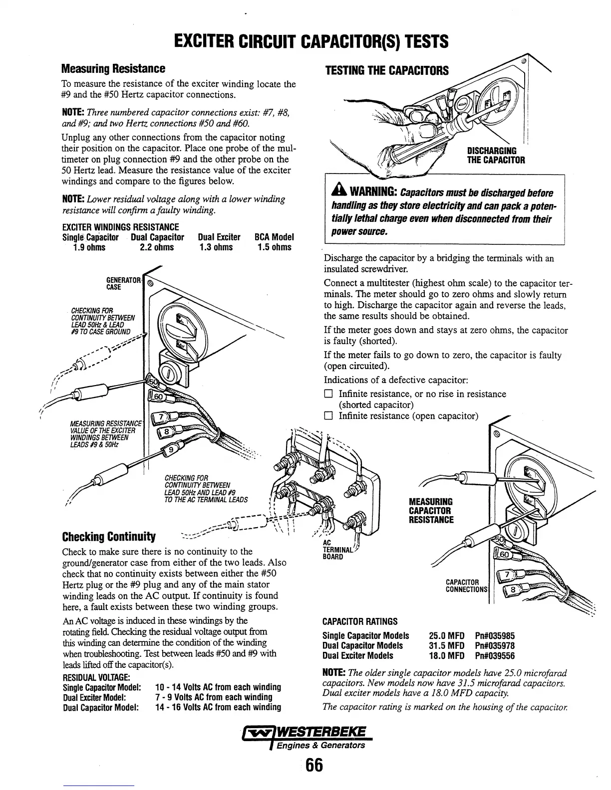
Measuring
Resistance
To
measure the resistance
of
the exciter winding locate the
#9 and the
#50 Hertz capacitor connections.
NOTE:
Three
numbered capacitor connections exist:
#7,
#8,
and #9; and
two
Hem
connections #50 and
#60.
Unplug any other connections from the capacitor noting
their position on the capacitor. Place one probe
of
the mul-
timeter on plug connection
#9
and the other
probe
on the
50 Hertz lead. Measure the resistance value
of
the exciter
windings and compare to
the
figures below.
NOTE:
Lower residual voltage along with a lower winding
resistance
will
confinn a faulty winding.
EXCITER
WINDINGS
RESISTANCE
SingllfCapacitor
Dual
Capacitor
Dual
Exciter
BCA
Model
1.9
ohms
2.2
ohms
1.3
ohms
1.5
ohms
CHECKING
FOR
CONTINUITY
BETWEEN
LEAD
50Hz
&
LEAD
19
TO
CASE
GROUND
_
.,;:'"
...
,
...
-\...;,
...
~,
TESTING
THE
CAPACITORS
A
WARNING:
Capacitors
must
be
discharged
before
handling
as
they
store
electricity
and
can
pack
a
poten-
tially
lethal
charge
even
when
disconnected
from
their
power
source.
Discharge the capacitor
by
a bridging the terminals with an
insulated screwdriver.
Connect a multitester (highest
ohm
scale) to the capacitor ter-
minals.
The
meter
should
go
to zero ohms
and
slowly return
to high. Discharge the
capacitor
again and reverse the leads,
the
same
results should
be
obtained.
lithe
meter goes down
and
stays at zero ohms, the capacitor
is faulty (shorted) .
,i~~'"''
..
-;~"
If
the
meter
fails to go
down
to zero, the capacitor is faulty
(open circuited) .
Indications
of
a defective capacitor:
I ,
/ (
, '
,
I'
CHECKING
FOR
CONTINUITY
BETWEEN
LEAD
50Hz
AND
LEAD
19
TO
THE
AC
TERMINAL
LEADS
Checking
Continuity
Check to make sure there is no continuity to the
ground/generator
case
from either
of
the two leads. Also
check that no continuity exists between either the
#50
Hertz plug or the
#9
plug
and
any
of
the main stator
winding leads on
the
AC
output.
If
continuity is found
here, a fault exists
between
these two winding groups.
An
AC voltage is induced in these windings by the
rotating
field.
Checking the residual voltage output from
this
winding can determine the condition
of
the winding
when
troubleshooting. Test between leads #50 and #9 with
leads
lifted off the capacitor(s).
RESIDUAL
VOLTAGE:
Single
CapaCitor
Model:
Dual
Exciter
Model:
Dual
CapaCitor
Model:
10
-14
Volts
AC
from
each
winding
7 - 9
Volts
AC
from
each
winding
14
-16
Volts
AC
from
each
winding
o Infinite resistance, or no rise in resistance
(shorted capacitor)
o Infinite resistance (open capacitor)
CAPACITOR
RATINGS
Single
Capacitor
Models
Dual
Capacitor
Models
Dual
Exciter
Models
MEASURING
CAPACITOR
RESISTANCE
25.0
MFD
Pn#035985
31.5
MFD
Pn#035978
18.0
MFD
Pn#039556
NOTE:
The
older single capacitor models have 25.0 microfarad
capacitors. New models now have
31.5 microfarad capacitors.
Dual exciter models have a
18.0 MFD
capacity.
The
capacitor rating
is
marked on
the
housing
of
the
capacitor.
Engines & Generators
66