4-5
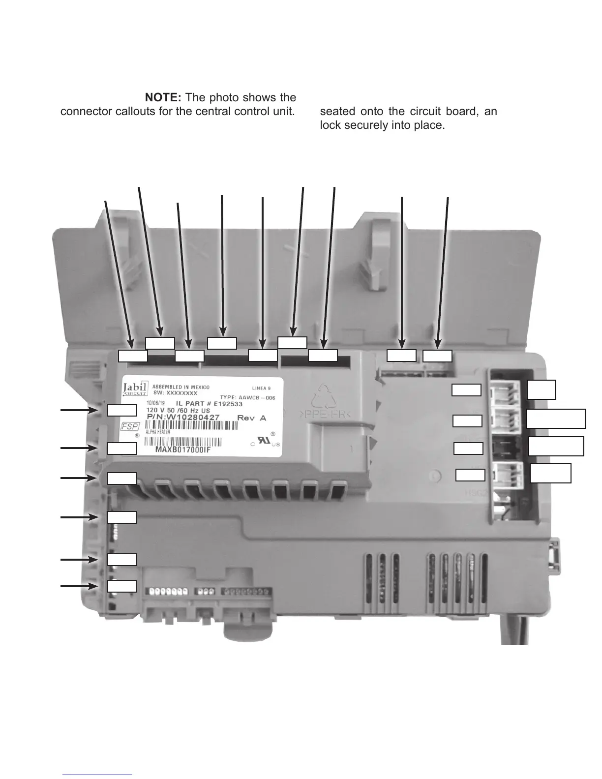
REMOVING THE CENTRAL CONTROL UNIT (continued)
REASSEMBLY NOTE: The photo shows the
connector callouts for the central control unit.
Make sure that all connectors are firmly
seated onto the circuit board, and that they
lock securely into place.
DCS3
SET2
UP3
UI7
MI3
FAC3
PS8
TH4
FM3
DI6
DL3
DP2
RP2 VCH7
VFS2
MS2
IF2
DLS2
HE2
Door
Closed
Switch
Pressure
Sensor/
Switch
MCU
Power
Interference
Filter
Door
Lock Switch
Heater
Element
Temperature
Sensor
Not
Used
Not
Used
User
Interface
MCU
Communi-
cations
Not
Used
Flow
Meter
(steam
model)
Detergent
Dispenser
Motor
Door
Lock
Coil
Drain
Pump
Vent
Fan
Hot /
Cold
Valves
Steam Valve
(steam
model)