Unsuccessful Ac�va�on
�
�
USER INTERFACE TEST
User Interface Test
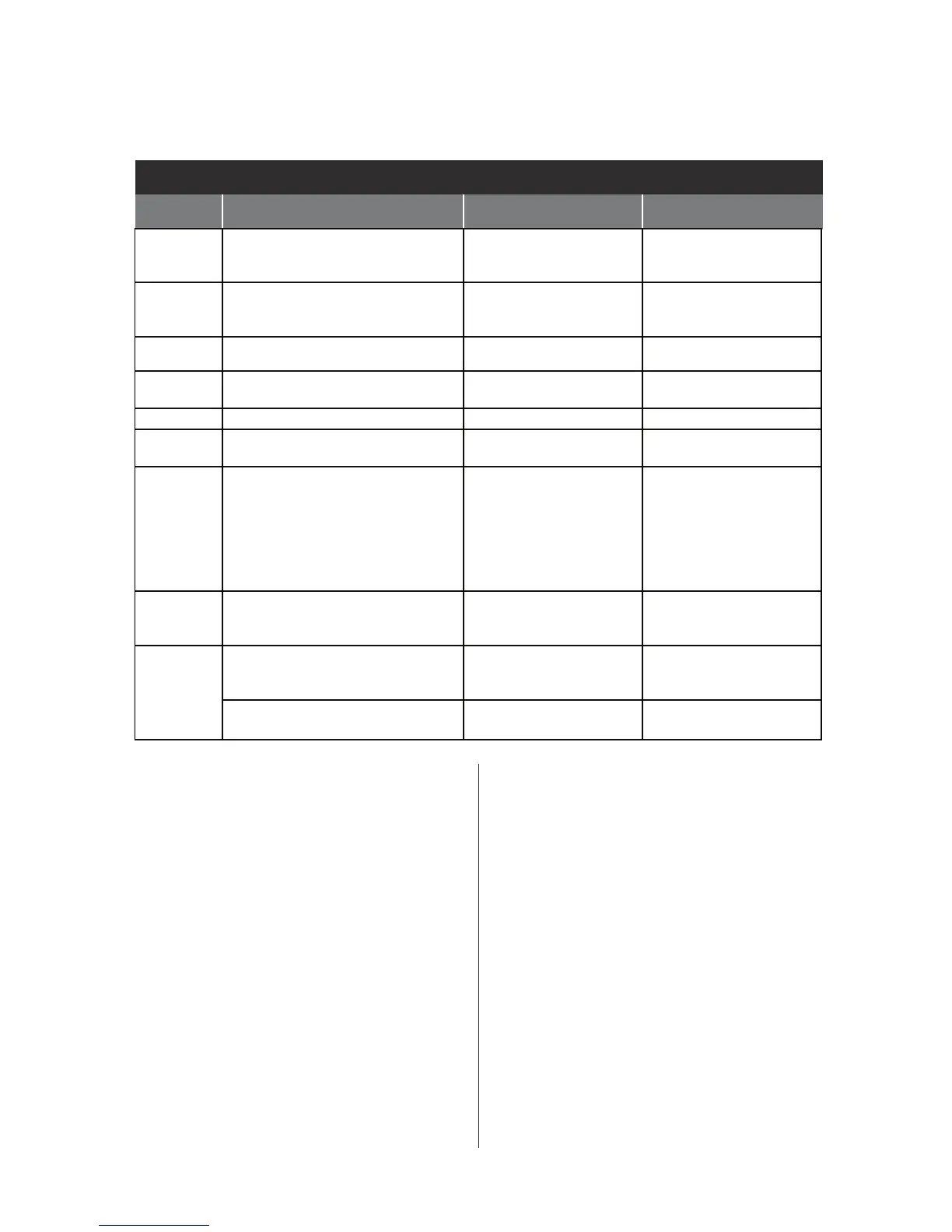
QUICK DIAGNOSTICS
QUICK DIAGNOSTIC TEST
TEST
PHASE
WA SHER FUNCTION COMPONENT STEP ENDS…
C00 Door lock motor is actuated. Door
unlocks, and then locks again.
Pump is activated for 15 seconds.
*Door lock system
*Drain Pump
on completion only.
C01 Heater is turned on.
Steam valve is actuated.
* Heater
* Steam Valve
* Te mperature Sensor
on completion or at key press.
C02 Cold water valve will actuate. * Flow Meter
* Cold Water Valve
on completion or at key press.
C03 Dispensing system is set to the
Prewash position.
*Dispenser Motor
*Dispenser Contact
on completion only.
C04 Hot water valve will actuate. * Hot Water Valve on completion or at key press.
C05 Drum rotates clockwise at wash
speed.
* Motor
* Motor Control Unit (MCU)
on completion or at key press.
C06 Heater is turned on.
Drum rotates clockwise at wash speed.
The water valve is activated to fill
drum to minimum water volume
required to wash. (If there is enough
water in the drum, the water valve
will not turn on.)
*Heater
*Water Te mperature
Sensor
*Pressure Sensor
on completion or at key press.
C07 Drain Pump is actuated until there is
no water in the system—plus an
additional 15 seconds.
* Drain Pump
* Pressure Sensor
on completion only.
C08 Drum rotates counterclockwise
from 35 rpm > 100 rpm > 150 rpm >
100 rpm in 4 minutes.
* Motor
* Motor Control Unit
on completion only.
Drum rotates counterclockwise
at maximum speed.
* Motor
* Motor Control Unit
on completion or at key press.
SOFTWARE VERSION DISPLAY
NOTE: The Soware Version Display mode will
me out aer 5 minutes of user inacvity and
return to standby mode.
Entry Procedure
To enter Soware Version Display, press
and hold the 2nd buon used to acvate the
Service Diagnosc mode for 5 seconds.
Press the START buon to cycle through the
following informaon:
• CCU (Soware Version, EEPROM Version)
• UI (Soware Version, EEPROM Version)
• MCU (Soware Version)
Exit Procedure
Press the POWER buon to exit Soware
Version Display and return to standby mode.
FAULT/ERROR CODES
(Refer to fault/error code charts on pages 8–10.)
Fault/Error Code Display Method
Fault codes are displayed by alternately
showing F# and E#. All fault codes have an
F# and an E#. The F# indicates the suspect
System/Category. The E# indicates the
suspect Component system.