WIKA operating instructions, model CEP6000
MM/YYYY country code based on 10/2014 GB/CN
GB
F1
HOME
7
F2 F3
89CE
E
N
T
E
R
4
1
MEASURE / SOURCE
3W
mA+
TC
V
mA
Loop
+
V
Hz
–
+
–
5
2
0
6
3
.
4W
mA–
MEASURE
–
CEP6000
Ω
1
2
3
4
6
8
9
7 5
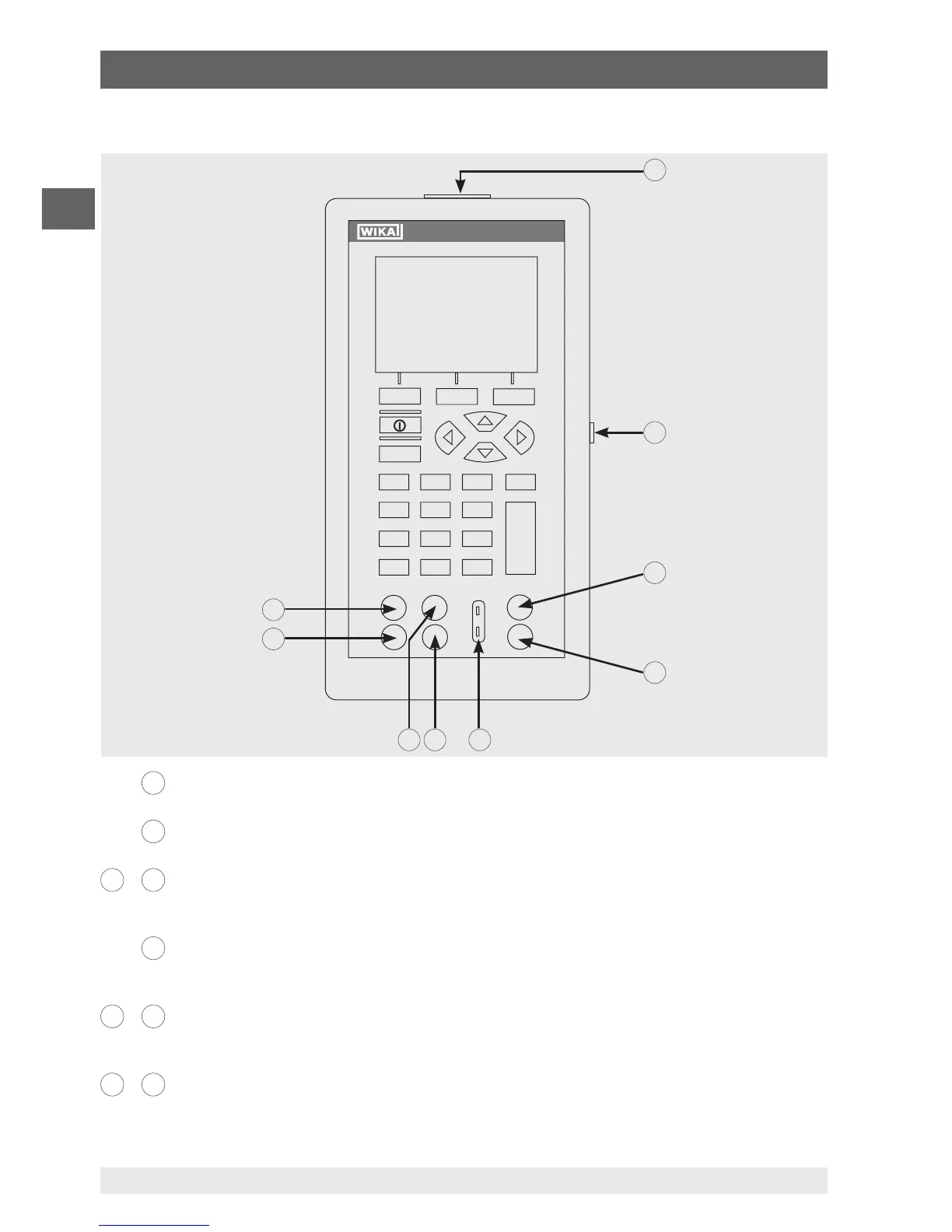
4.1.1 Connections
1
Connection for external pressure module
Connects the calibrator with a pressure module for pressure measurement.
2
Serial interface
Connects the calibrator with a PC for remote operation.
3
+
4
(Isolated) Current and voltage input as well as for output of DC 24 V voltage
supply
Terminals for the measurement of current, voltage and separate current loop supplies.
5
Thermocouple input/output
Terminal for the measurement or simulation of thermocouples. Suitable for polarised
miniature connectors for thermocouples.
6
+
7
Voltage, resistance thermometers (2-wire), frequency, pulse, input/output
Terminals for the simulation and measurement of voltage, frequency, pulse trains and
resistance thermometers (RTDs).
8
+
9
Current, resistance thermometers (3-wire, 4-wire), input/output
Terminals for the simulation and measurement of current and also for resistance thermom-
eter measurements with 3- and 4-wire connection.
4. Design and function