WIKA operating instructions, model CEP6000
MM/YYYY country code based on 10/2014 GB/CN
GB
F1
HOME
7
F2 F3
89CE
E
N
T
E
R
4
1
MEASURE / SOURCE
3W
mA+
TC
V
mA
Loop
+
V
Hz
–
+
–
5
2
0
6
3
.
4W
mA–
MEASURE
–
CEP6000
Ω
–
+
Calibrating an I/P instrument
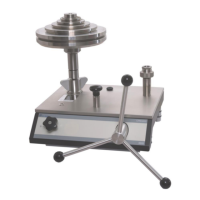
Pressure module
and pressure
module adapter
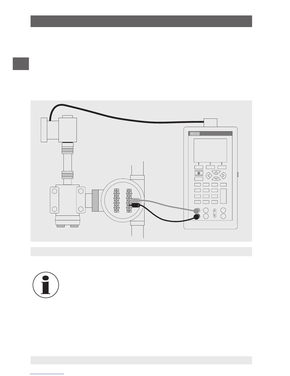
6.7.2 Calibrating an I/P instrument
To calibrate pressure-controlling instruments, follow the steps below:
1. In the main menu, switch to the upper display “UPPER” and select “PRESSURE”.
2. In the main menu, switch to the lower display “LOWER” and select “mA”.
3. The input/output setting must be set to “OUT”.
4. Connect the calibrator to the sensor using the mA output (see following figure).
5. Enter the current value via the keypad.
The calibrator simulates the transmitter current and measures the output
pressure with an external pressure module.
6.7.3 Calibrating a transmitter
To calibrate a transmitter, both displays (“UPPER” and “LOWER”) are used - the upper
display for measurement and the lower for output/simulation. In this example, a thermo-
couple transmitter is calibrated.
6. Commissioning, operation