WIKA operating instructions, model CEP6000
MM/YYYY country code based on 10/2014 GB/CN
GB
MEASURE / SOURCE
3W
mA+
TC
V
mA
Loop
+
V
Hz
–
+
4W
mA–
MEASURE
–
–
+
+
–
Ω
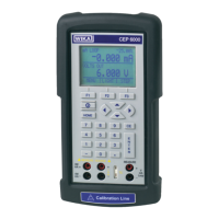
Simulating the temperature at the thermocouple terminal
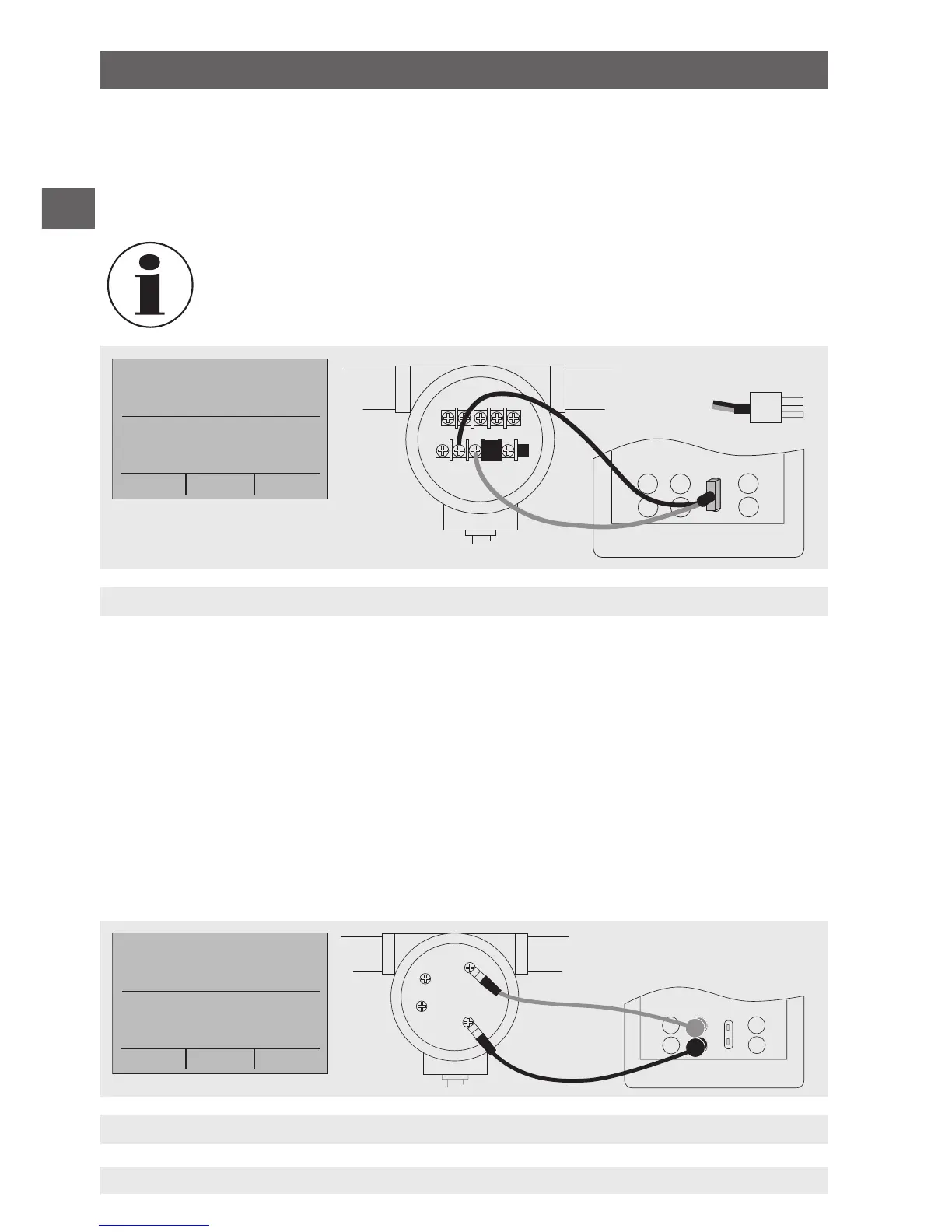
Simulating resistance or resistance thermometers
Thermocouple plug
3. The input/output setting must be set to “OUT”.
4. Select the corresponding thermocouple model in the menu.
5. Select temperature unit.
6. Enter the temperature value or voltage value, respectively, via the keypad.
Used thermocouple wire must match the thermocouple type being
calibrated.
6.5.9 Simulating resistance or resistance thermometers
To simulate a resistance/resistance thermometer, follow the steps below:
1. Connect the wires of the RTD type to the input/output of the calibrator (see following
figure).
2. In the main menu, switch to the lower display “LOWER” and select “RTD”.
3. The input/output setting must be set to “OUT”.
4. Select the corresponding RTD type in the menu.
5. Select temperature unit.
6. Enter the temperature value or resistance value, respectively, via the keypad.
6. Commissioning, operation