Measuring voltage and frequency with the input and output terminals
6.2.11 Menu function “Parameter selection”
The menu for parameter selection is called via the main menu using “UPPER” or
“LOWER”. The options are “SELECT”, “NEXT” and “DONE”. When selected, one param-
eter flashes in the display.
Using the option “SELECT”, the parameter can be altered. With the option “NEXT”, one
can switch to another variable. “DONE” switches back to the start menu and accepts the
selection.
6.3 Cursor control/set point control
The output value can be changed using the four arrow keys on the keypad. If an arrow key
is pressed, a cursor appears under the last digit of the output value. Use the left and right
arrow buttons to select which digit in the output value should be changed. With the up
and down arrow keys, the output value can be increased or decreased. The menu bar will
change to the set point menu, as soon as one of the four arrow keys is pressed.
The three function keys are assigned the values “0 %”, “25 %” and “100 %”. The value for
0 and 100 % can be saved through the input of a value, when the corresponding function
key is held down at the same time. The key for “25 %” then switches to the value corre-
sponding to 25 %.
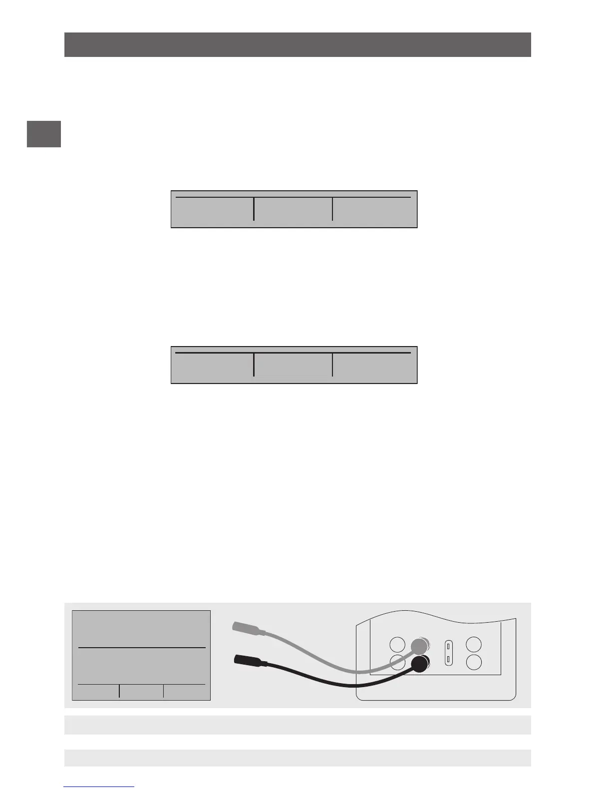
6.4 Using the measuring modes (lower display)
6.4.1 Measuring voltage and frequency
To measure voltage or frequency, follow the steps below:
1. In the main menu, switch to the lower display “LOWER” and select “V” or “FREQ”.
2. The input/output setting must be set to “IN”.
3. Connect the test cables (see following figure).
SELECT NEXT DONE
0% 25% 100%
6. Commissioning, operation