WIKA operating instructions, model CEP6000
MM/YYYY country code based on 10/2014 GB/CN
GB
MEASURE / SOURCE
3W
mA+
TC
V
mA
Loop
+
V
Hz
–
+
4W
mA–
MEASURE
–
Ω
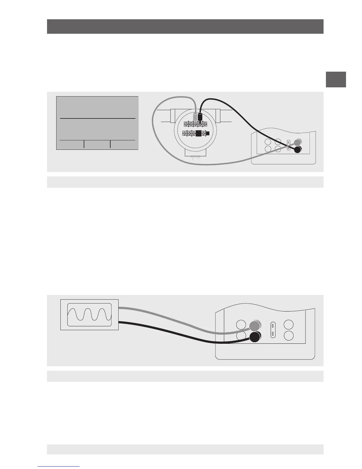
Isolated input
Connection of a display instrument
Maximum current: 1 mA
To measure current with a DC 24 V voltage supply on the isolated input channel,
follow the steps below:
1. In the main menu, switch to the upper display “UPPER” and select “mA LOOP”.
2. Connect the test cables to the calibrator’s isolated inputs (see following figure).
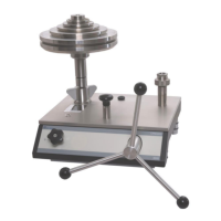
6.7 Using the upper and lower displays for test and calibration
6.7.1 Calibrating a display instrument
To calibrate recording and display instruments using the output functions, follow
the steps below:
1. In the main menu, switch to the lower display “LOWER” and select the corresponding
parameter.
2. The input/output setting must be set to “OUT”.
3. Connect the test cables to the calibrator (see following figure).
6. Commissioning, operation