Isolated input
below 0 °C. For the range above 0 °C, only the coefficients A and B are required, so
coefficient C is then set to 0. R
0
is the resistance of the probe at 0 °C.
Coefficients for Pt385, Pt3926 and Pt3616
RTD Range R0 Coefficient A Coefficient B Coefficient C
Pt385 -260 ... 0 °C 100 3.9083 x 10
-3
-5.775 x 10
-7
-4.183 x 10
-12
Pt385 0 ... 630 °C 100 3.9083 x 10
-3
-5.775 x 10
-7
-
Pt3926 Under 0 °C 100 3.9848 x 10
-3
-5.87 x 10
-7
-4 x 10
-12
Pt3926 Above 0 °C 100 3.9848 x 10
-3
-5.87 x 10
-7
-
Pt3916 Under 0 °C 100 3.9692 x 10
-3
-5.8495 x 10
-7
-4.2325 x 10
-12
Pt3916 Above 0 °C 100 3.9692 x 10
-3
-5.8495 x 10
-7
-
6.6 Using the isolated measuring modes (upper display)
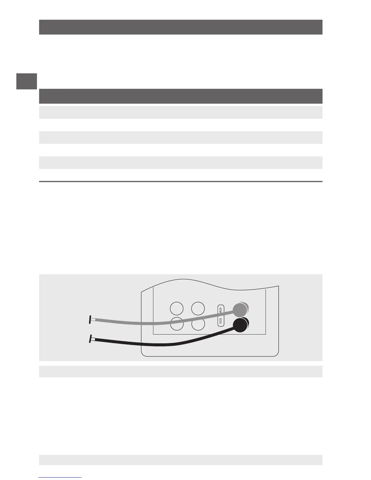
6.6.1 Measuring voltage (V) or current (mA)
To measure voltage or current on the isolated input channel, follow the steps
below:
1. In the main menu, switch to the upper display “UPPER” and select “V” or “mA”.
2. Connect the test cables to the calibrator’s isolated inputs (see following figure).
6.6.2 Current measurement with DC 24 V voltage supply
To test a 2-wire transmitter, which has an external power supply that is not connected,
use the function for separate voltage supply. This function activates a DC 24 V voltage
supply in series with the measuring current loop.
6. Commissioning, operation