WIKA operating instructions, model CEP6000
MM/YYYY country code based on 10/2014 GB/CN
GB
3W
4W
1
1
2
2
3
3
4
4
MEASURE / SOURCE
3W
mA+
TC
V
mA
Loop
+
V
Hz
–
+
4W
mA–
MEASURE
–
MEASURE / SOURCE
3W
mA+
TC
V
mA
Loop
+
V
Hz
–
+
4W
mA–
MEASURE
–
Ω Ω
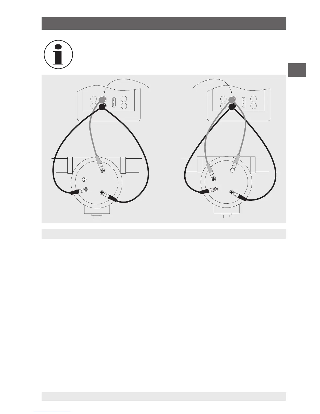
3- or 4-wire connection for RTDs
Use stackable test
cables for common
terminals
The calibrator simulates an RTD probe with 2-wires. To connect a probe
with 3- or 4-wires, use the stackable test cables (see following figure).
6.5.9.1 Customer-specific resistance thermometer (RTD)
To achieve the highest possible accuracy, it is possible to load probe-specific resistance
thermometer coefficients into the calibrator.
To enter probe-specific coefficients, follow the steps below:
1. In the main menu, switch to the lower display “LOWER” and select “RTD”.
2. Select RTD type “CUSTOM”.
3. Select menu function “Probe-specific coefficients”.
4. Enter the values requested by the calibrator using the keypad.
▶
Minimum temperature
▶
Maximum temperature
▶
R
0
▶
Temperature coefficients
The custom function uses the Callendar–Van Dusen equation for output and measure-
ment of custom resistance thermometers. The coefficient C is used only for temperatures
6. Commissioning, operation