WIKA operating instructions, model CEP6000
MM/YYYY country code based on 10/2014 GB/CN
GB
MEASURE / SOURCE
3W
mA+
TC
V
mA
Loop
+
V
Hz
–
+
4W
mA–
MEASURE
–
–
–
+
+
UUT
Ω
mA IN
0.000 mA
-25.00%
mA 2W SIM
MENU
4.000 mA
LIGHT
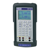
Connection for the transmitter simulation
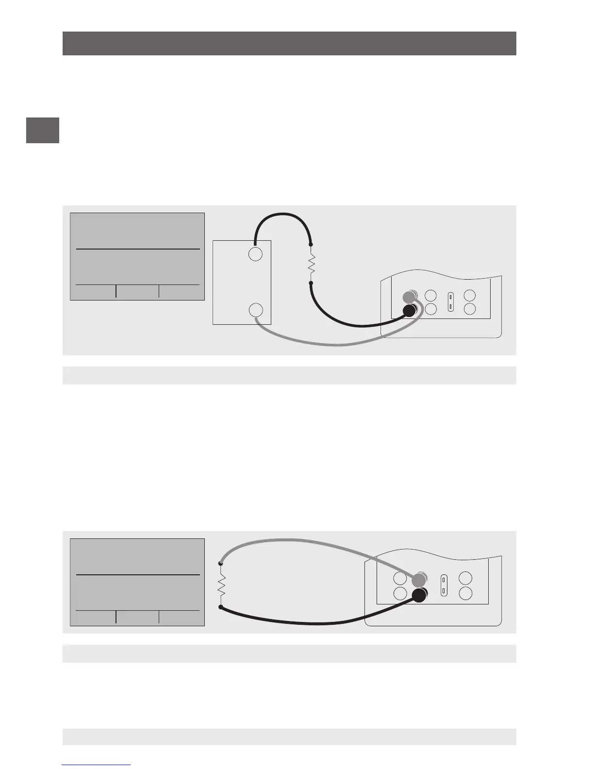
Connections for voltage, frequency and pulse outputs
30 V max.
Voltage
supply
6.5.4 Simulating a transmitter
To use the calibrator to simulate a transmitter in a current loop, follow the steps
below:
1. In the main menu, switch to the lower display “LOWER” and select “mA 2W SIM”.
2. Enter the desired current with the keypad.
3. Connect the test cables to the terminals for current input (see following figure).
3. Connect the external DC 24 V voltage supply (see following figure).
6.5.5 Voltage output
To output a voltage, follow the steps below:
1. In the main menu, switch to the lower display “LOWER” and select “VOLTS”.
2. The input/output setting must be set to “OUT”.
3. Connect the test cables to the terminals for voltage output (see following figure).
4. Enter the desired voltage value via the keypad.
6. Commissioning, operation