WIKA operating instructions, model CEP6000
MM/YYYY country code based on 10/2014 GB/CN
GB
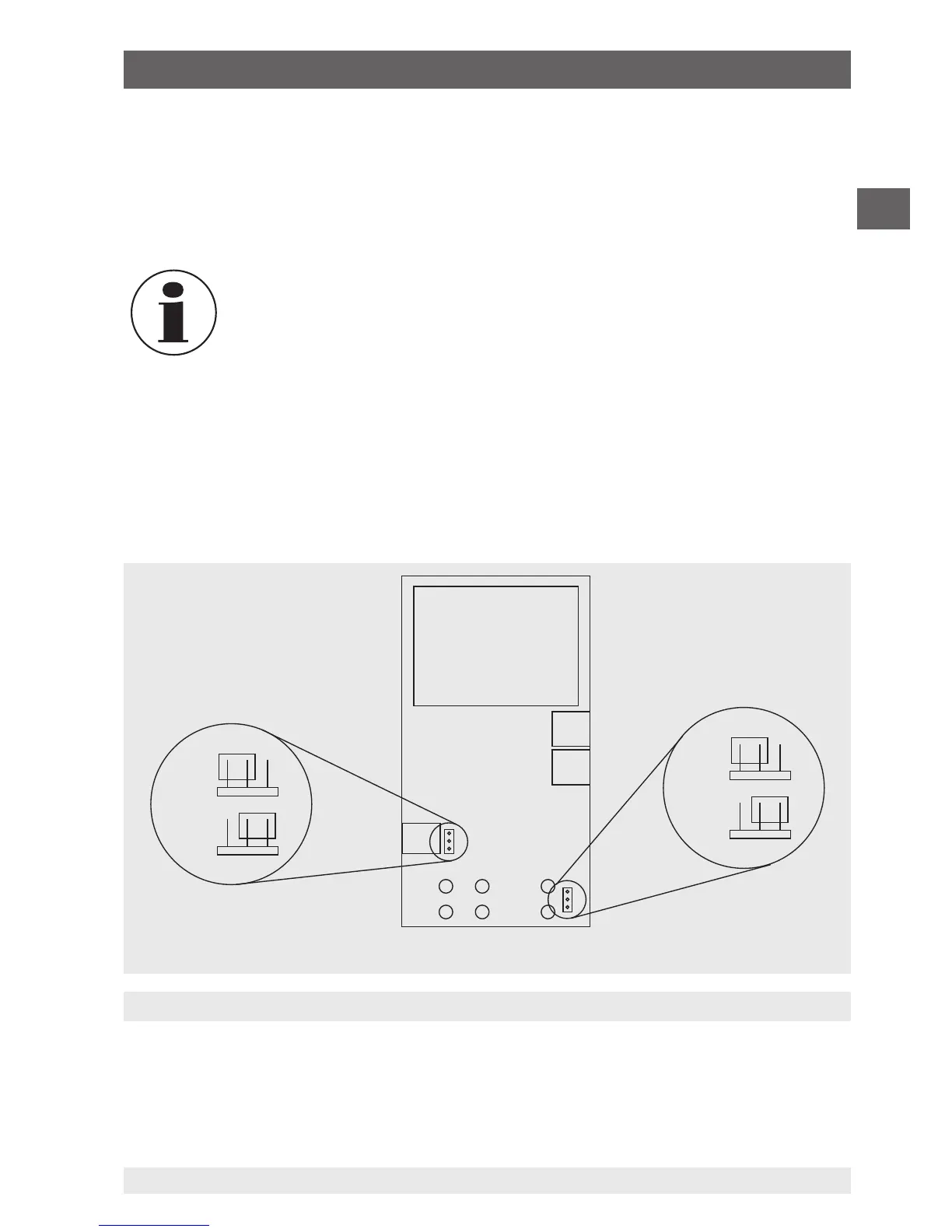
Position of the HART™ jumpers
HART™ resistor
Circuit board
6.5.3.1 HART™ resistor selection
The CEP6000 can be configured so that the 250 Ω resistor for HART™ compatible
instruments can be activated within the CEP6000. If the internal 250 Ω resistor within the
CEP6000 is used, a serial resistance for the calibration of HART™ modules must not be
activated.
When using the internal 250 Ω resistor, the maximum load resistance is
reduced from 1,000 Ω to 750 Ω, at a current of 20 mA.
6.5.3.2 HART™ resistor, activation/deactivation procedure
1. Remove the battery cover and loosen both of the screws on the upper part of the case.
2. Remove both of the screws on the lower part of the case.
3. Carefully remove the upper half of the case from the lower half.
The following picture indicates the position of the HART™ jumpers.
6. Commissioning, operation
OFF
OFF
ON
ON
 Loading...