MEASURE / SOURCE
3W
mA+
TC
V
mA
Loop
+
V
Hz
–
+
4W
mA–
MEASURE
–
+
–
Ω
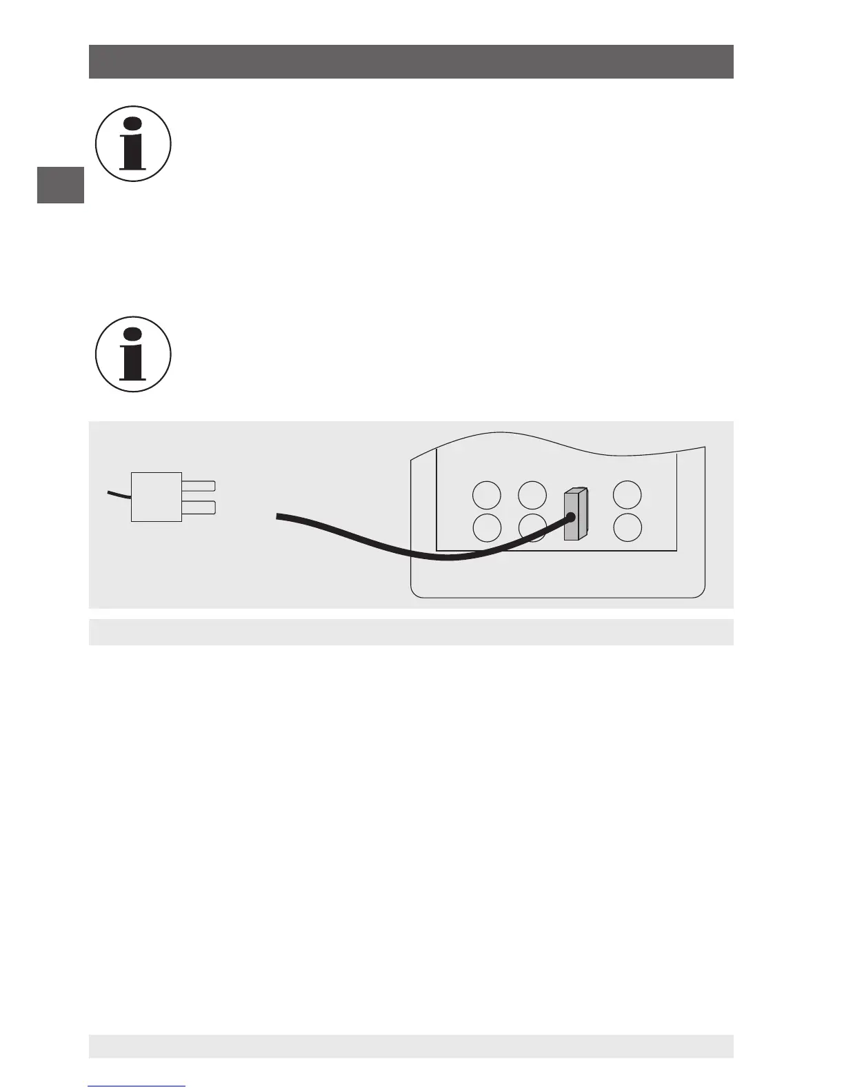
Measurement of the temperature at the thermocouple terminal
Thermocouple plug
The connecting cable for the thermocouple must match the type of the
thermocouple being calibrated.
2. In the main menu, switch to the lower display “LOWER” and select “TC”.
3. The input/output setting must be set to “IN”.
4. Select the corresponding thermocouple model in the menu.
5. Select temperature unit.
In the interests of optimum accuracy, wait 2 to 5 minutes so that the
temperature between the mini-connector and the calibrator stabilises.
After this, carry out the measurement.
The calibrator can measure the voltage of the thermocouple in mV, so that the tempera-
ture can be determined with the aid of a table if the corresponding thermocouple type is
not supported by the calibrator. For the case described above, proceed and select “mV”
as the type.
6.4.3.2 Using resistance thermometers (RTDs)
The supported resistance thermometers are detailed in the specifications in chapter
10 “Specifications”. The specific characteristic of RTDs is their temperature-dependent
resistance (R0). The calibrator can work with input signals with 2-, 3- or 4-wires, where
input measurements with 4-wire connection are the most accurate.
To measure temperature with resistance thermometers, follow the steps below:
1. In the main menu, switch to the lower display “LOWER” and select “RTD”.
2. The input/output setting must be set to “IN”.
3. Select 2-, 3- or 4-wire connection “2W, 3W, 4W”.
6. Commissioning, operation