POSITIONIT POSITIONERS
PM-01011-A 2-3
October 2023
2.5 Mounting the Positioner
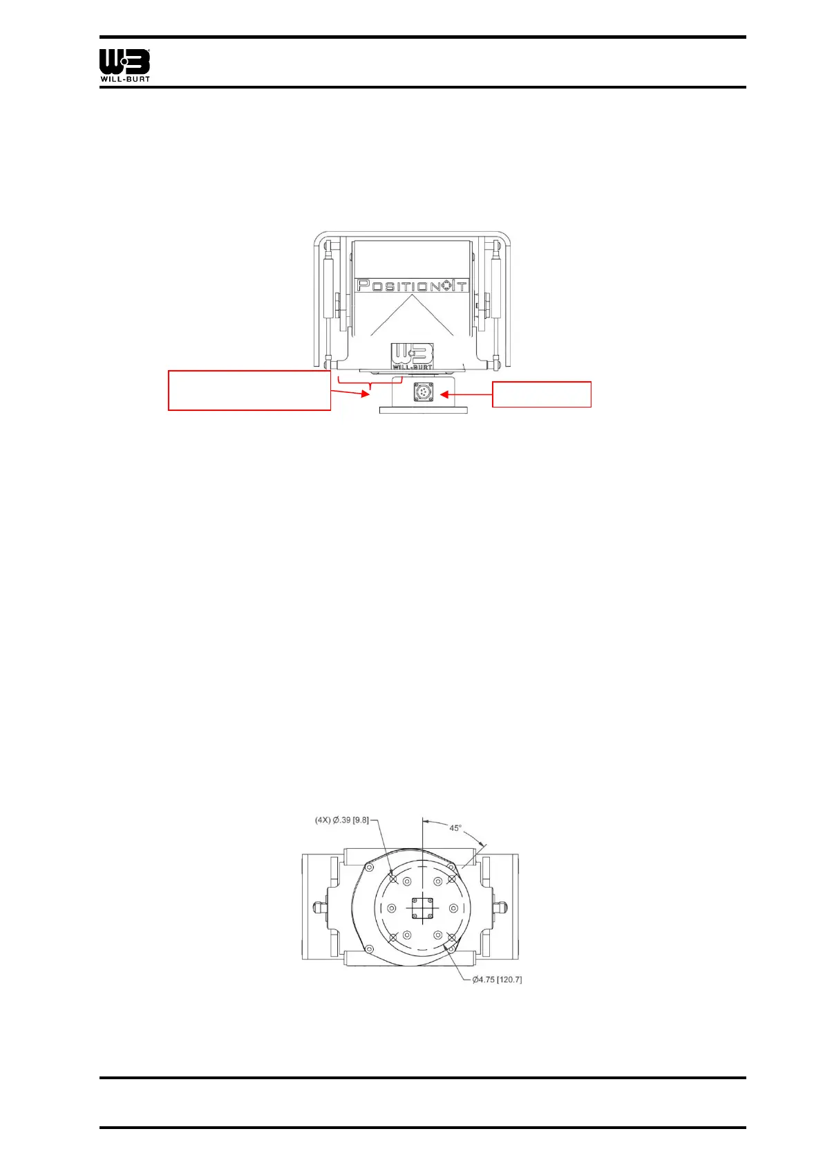
When installing, the front of the positioner can be identified as the side of the positioner
opposite of the side egress on the mounting pedestal while the positioner is in the home
position (Figure 2-1). Note that the offset on the left of the positioner, as you face the side
egress, is wider than the offset to the right. The positioner ships in the home position.
Figure 2-1 Rear of Positioner (PI-150 Shown)
The mounting location must:
• Be capable of withstanding the holding forces required by the bolts
• Be located on level terrain
• Be free of obstructions
• Allow for full pan and tilt movement
• Have the positioner base face down. Do not mount the positioner upside down.
Be sure to take into consideration other external factors, such as wind or ice loading, when
selecting a mounting location. Make sure that these external factors do not overload the
system.
Reference Figure 2-2 for the mounting hole locations for the system. There are (4) holes
equally spaced. Connect the positioner to the top of the mast with (4) high-strength ⅜ in. or
M8 stainless steel bolts and nuts (customer supplied). Torque all hardware as appropriate
for its material and size. The mounting hardware must include proper means to resist
vibration loosening such as thread-locking compound or locking hardware.