en Installation
64 WILO SE 2018-12
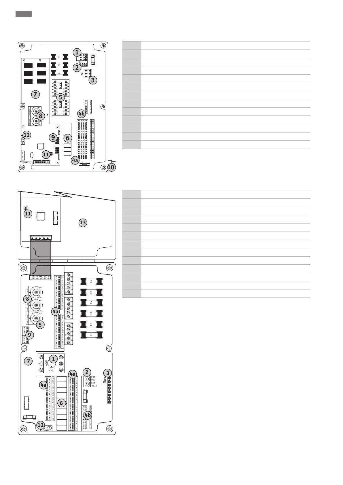
6.5.1 Overview of components
Fig.2: Control EC-L 1.../EC-L 2...
1 Terminal strip: Mains connection
2 Adjustment mains voltage
3 Terminal strip: Earth (PE)
4a Terminal strip: Sensors
4b Terminal strip: Sensors for active ex-mode
5 Contactor combinations
6 Output relay
7 Control board
8 Potentiometer for motor current monitoring
9 ModBus: RS485 interface
10 Dynamic pressure bell pressure connection (“IPS” version only)
11 ModBus: Jumper for termination/polarisation
12 Slot for 9V rechargeable battery
Fig.3: Control EC-L 3...
1 Main switch
2 Adjustment mains voltage
3 Terminal strip: Earth (PE)
4a Terminal strip: Sensors
4b Terminal strip: Sensors for active ex-mode
5 Contactor combinations
6 Output relay
7 Control board
8 Potentiometer for motor current monitoring
9 ModBus: RS485 interface
11 ModBus: Jumper for termination/polarisation
12 Slot for 9V rechargeable battery
13 Housing cover