12
WPS-365-DVR-9CH & 16CH Installation and Users Manual
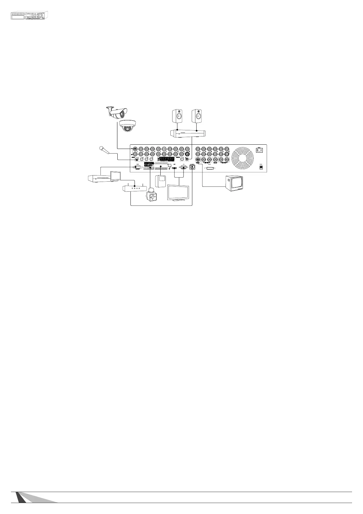
3.2. CONNECTIONS
To ensure proper performance and operation of the 365 DVR, it is recommended that all connections
and setup be performed by a qualied system installer.
3.2.1. BASIC CONNECTIONS
Amplifier
Router
Automation System
Motion Sensor(s)
Siren
LCD Monitor/Flat Panel TV
CRT Monitor
Camera(s)
Microphone
Speakers
WPS-365 Series DVR
• POWER
Connect the included External Power Supply to surge protection or wall outlet.
• CAMERAS
Connect the video output from cameras or other composite video sources using coaxial cable to the
Video In connectors. Set each of the DIP switches to ON unless the corresponding video output terminal is
connected.
• MAINMONITOR/VGAOUTPUT
Connect the Main Monitor BNC to a surveillance TV monitor
Connect the Main Monitor VGA output to a VGA monitor or Flat Panel TV
Connect the Main Monitor HDMI Output to HD Flat Panel TV.
Main Monitor Notes
1. ForHDMIcompatibility,conrmthatthedisplaywillsupportaPCresolutionof1024x768at60Hz.Some
olderTVsandlowergradeTVsdonotsupportthisresolution.SomemodelTVsonlysupportthisresolution
ononeoftheHDMIinputs.CheckthemanualforthespecicationsoftheTV.AgoodindicatorisaVGA
connectionontheTV.
2. TheDVRwillscaletheimagetotheHDMIconnection,thiscancausethecompositeoutput(BNC)to
“overscan”andcutofftheedgesoftheimage.
3. TheHDMIconnectionmustbeconnectedpriortoturningDVRoninordertoactivatetheHDMIout
put connection.
3.2.2. OPTIONAL CONNECTIONS
• AUDIOINPUT
Connect the audio input connector to the audio line-out from line level microphones or other audio
sources. Please make sure to associate the audio inputs with a camera in the Camera Setup as described
in Section 6.2 accordingly. An audio input can only be associated with one camera.
• AUDIOOUTPUT
Connect the audio output connector to an amplier and speakers.
• ALARMINPUTS
Connect the alarm inputs to NC and/or NO sensors or security alarm panel relays. Please make sure to
setup the alarm congurations as described in Section 6.3 accordingly.
 Loading...