9
WPS-365-DVR-9CH & 16CH Installation and Users Manual
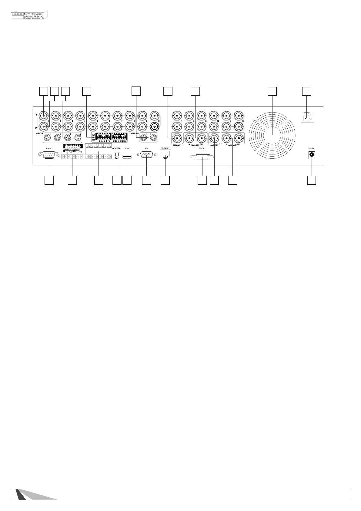
REAR PANEL, CONT’D.
1 2 3 4
5
6 7 8 9
10111213141516181920 17
10. Power Connection (DC IN)
Connect the supplied External Power Supply. Acceptable Range: 12V / 8.33A DC
11. CALL-AUX Connectors (CALL-AUX IN/OUT)
These connections are not used on this model.
12. Call Monitor Output Connector (CALL OUT)
Connect TV monitor to this BNC connector for call monitor display
13. ESATA
Connection to external drive or PC with an ESATA connection for additional storage.
14. Ethernet Connector
Connect to a 10/100Base-T Ethernet network for remote access and integrated control and video
streaming to Automation Systems.
15. VGA Connector
Main monitor display for connection to VGA monitor for setup, control and monitoring of cameras and
system.
16. HDMI (Main Out)
Main monitor display for connection to HDMI TV or monitor for setup, control and monitoring of cameras
and system.
17. NTSC/PAL Selector Switch
Sets the video output to NTSC or PAL-based on your local TV system.
18. Alarm Input Connectors (ALARM IN 1-16)
Connect to external devices such as motion sensors or door switches.
19. Alarm Out - RS-485 Connector
1- Alarm Output Connectors (ALARM OUT 1-4)
Connect to 2 Normally Closed (NC) alarm outputs (1-2) and 2 Normally Open (NO) alarm outputs (3-4).
2- RS-485 Connector
Connect to RS-422/485 compatible PTZ camera(s) or keyboard.
20. RS-232 Connector
Connection for data and control via an external control system such as Control4, Crestron or AMX.
 Loading...