5-45
ELEC
Electrical system
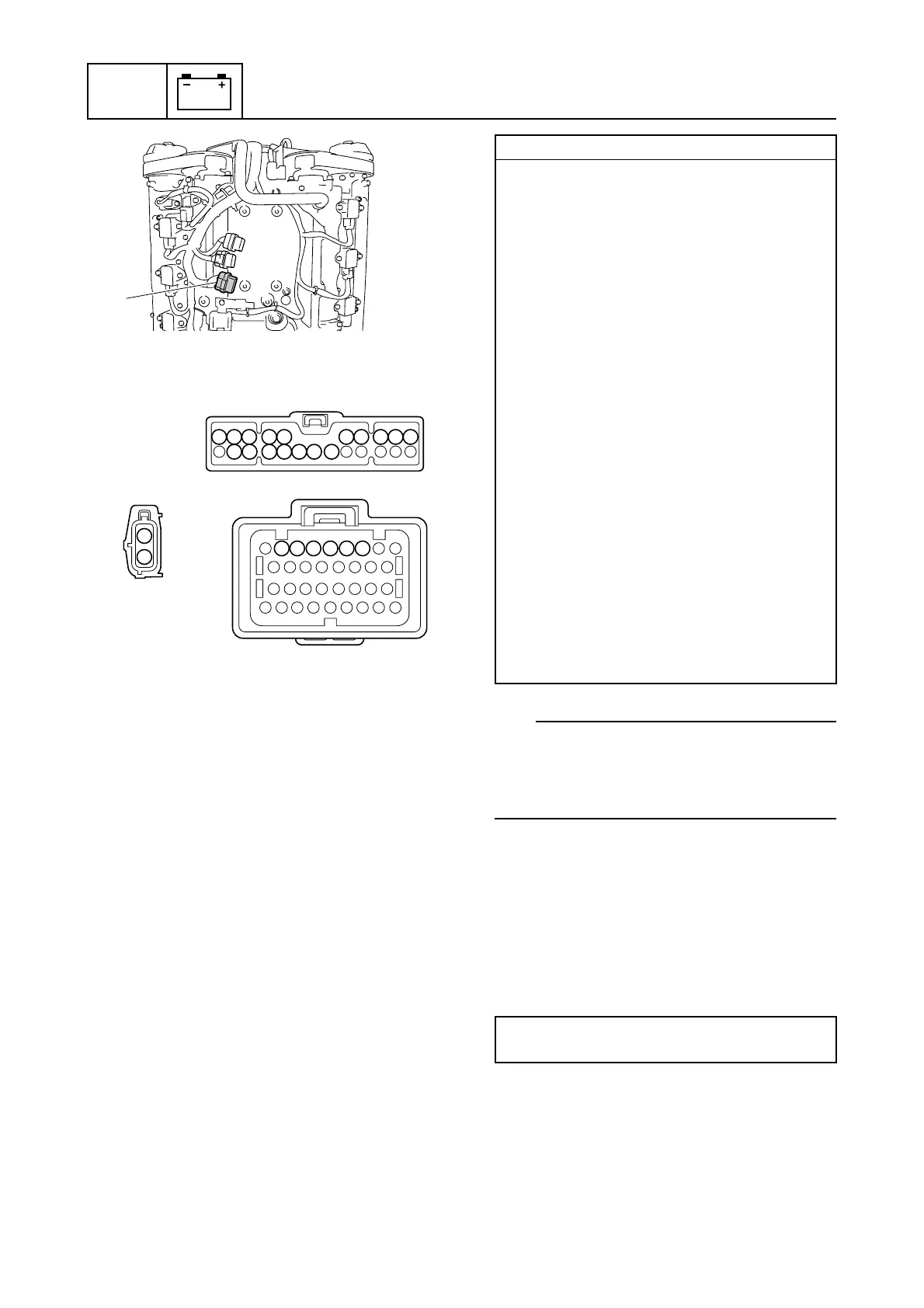
10. Check the wiring harness for continuity.
TIP:
Make sure that there is continuity between
terminal 1 of the fuel injector couplers a and
one of the terminals of the fuse holder cou-
pler b.
11. Connect the engine ECM coupler.
NOTICE: Make sure that the rubber
seal is installed properly in the engine
ECM coupler.
12. Install the engine ECM, and then tighten
the engine ECM bolts to the specified
torque.
13. Install the engine ECM cover.
14. Connect the fuse holder coupler, and
then install the fuse holder.
c
9
10
22 21 20 19 18 17 16
8 7 6 5 4 3 2 1
c
b
a
60 59 58 57 56 55
1
2
Wiring harness continuity:
Fuel injector #1
a Terminal 1–
b Terminals 1–10 and 16–22
a Terminal 2–c Terminal 59
Fuel injector #2
a Terminal 1–
b Terminals 1–10 and 16–22
a Terminal 2–c Terminal 60
Fuel injector #3
a Terminal 1–
b Terminals 1–10 and 16–22
a Terminal 2–c Terminal 58
Fuel injector #4
a Terminal 1–
b Terminals 1–10 and 16–22
a Terminal 2–c Terminal 57
Fuel injector #5
a Terminal 1–
b Terminals 1–10 and 16–22
a Terminal 2–c Terminal 56
Fuel injector #6
a Terminal 1–
b Terminals 1–10 and 16–22
a Terminal 2–c Terminal 55
Engine ECM bolt:
7 N·m (0.7 kgf·m, 5.2 ft·lb)


 To Next Page