5-60
5
15. Install the engine ECM cover.
16. Connect the engine temperature sensor
coupler.
17. Install the flywheel magnet. See “Install-
ing the flywheel magnet” (7-17).
18. Install the flywheel magnet cover.
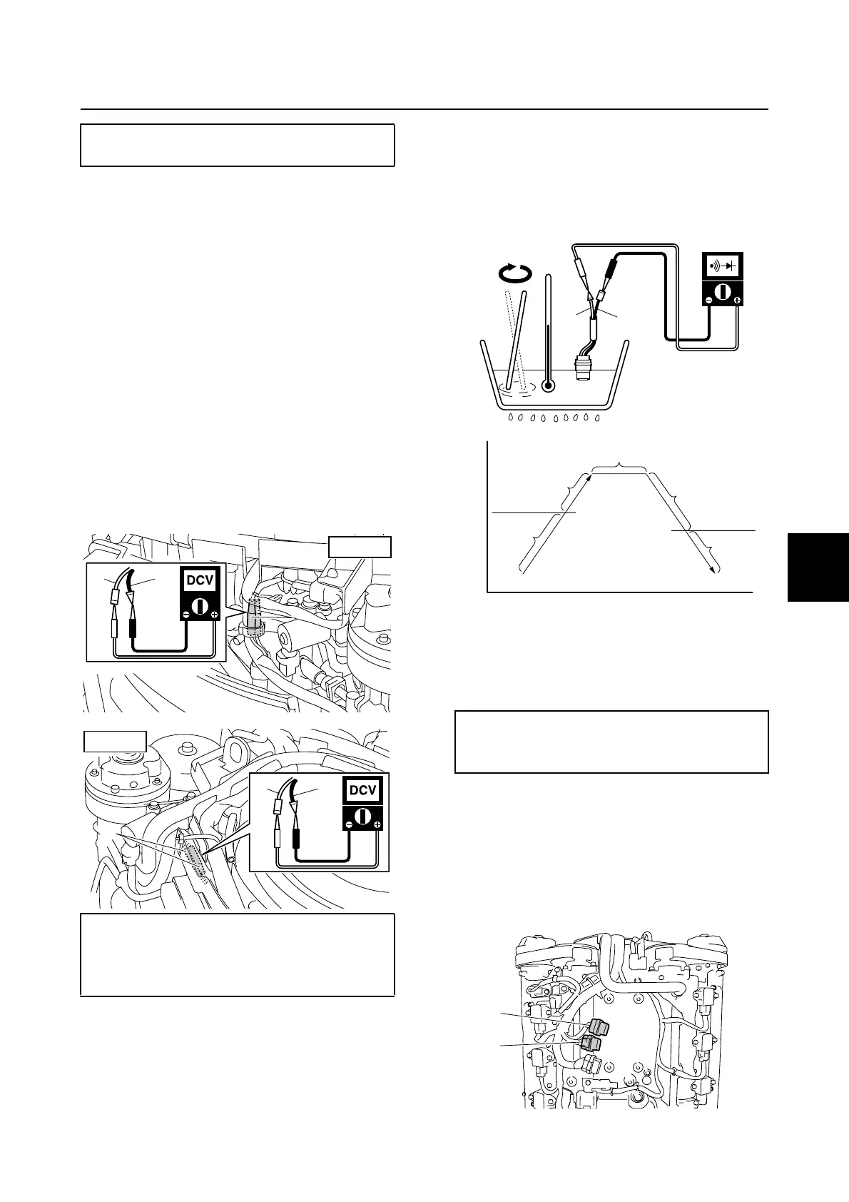
Checking the thermoswitch
1. Remove the flywheel magnet cover.
2. Disconnect the thermoswitch connectors.
3. Turn the engine start switch to ON, and
then measure the input voltage at the
thermoswitch connectors a and b.
4. Turn the engine start switch to OFF.
5. Remove the thermoswitches.
6. Place the thermoswitches in a container
of water and heat the water slowly.
7. Check the thermoswitches for continuity
at the specified temperatures. Replace if
out of specification.
c Temperature
d Time
e No continuity
f Continuity
8. Install the thermoswitches.
9. Remove the engine ECM cover.
10. Remove the engine ECM, and then dis-
connect the engine ECM couplers k and
m.
Engine ECM bolt:
7 N·m (0.7 kgf·m, 5.2 ft·lb)
Thermoswitch input voltage (reference
data):
Pink (P)–Black (B)
11.4 V
B
P
B
P
PORT
aa
B
P
b
STBD
Thermoswitch continuity temperature:
g: 84–90 °C (183–194 °F)
h: 68–82 °C (154–180 °F)
P
B
g
c
e
f
f
d
f
h
e
k
m
Ignition unit and component



 To Next Page