7-2
7
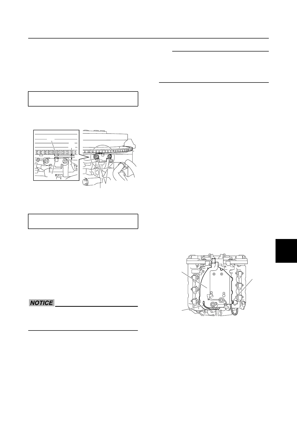
2. Turn the flywheel magnet clockwise to
align the protrusion a on the flywheel
magnet with the protrusion b on the
pulser coil.
3. Measure the pulser coil air gap c. Adjust
if out of specification.
4. Loosen the pulser coil screws 1 and
adjust the pulser coil air gap.
5. Tighten the pulser coil screws 1, and
then check the pulser coil air gap.
6. Install the wiring harness guide and wir-
ing harness guide bolts. See “Installing
the wiring harness” (7-23).
7. Install the flywheel magnet cover.
Checking the valve clearance
Measure the valve clearances when the
engine is cold.
Do not turn the flywheel magnet counter-
clockwise. Otherwise, the water pump
impeller could be damaged.
1. Reduce the fuel pressure. See “Reduc-
ing the fuel pressure” (6-7).
TIP:
When measuring or adjusting the valve clear-
ances, the fuel line must be disconnected, so
make sure to reduce the fuel pressure before
performing the disassembly procedure.
2. Remove the flywheel magnet cover and
engine ECM cover.
3. Remove the blowby hose. See “Remov-
ing the intake silencer” (6-17).
4. Remove the speed sensor coupler from
the bracket. See step 16 in “Removing
the power unit” (7-8).
5. Remove the wiring harness from the
engine ECM bracket and holder. See
steps 4–16 in “Removing the wiring har-
ness” (7-20).
6. Remove the ignition coils and spark
plugs.
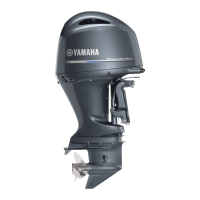
7. Disconnect the cooling water hose 1.
8. Remove the knock sensor lead a from
the engine ECM bracket 2.
9. Remove the engine ECM bracket 2.
10. Turn the flywheel magnet clockwise and
align the “1TDC” mark b on the flywheel
magnet with the pointer c.
11. Check that the “II” marks d on the VCT
assembly (PORT) and driven sprocket
(PORT) are aligned, and check that the
“I” marks e on the VCT assembly
(STBD) and driven sprocket (STBD) are
aligned.
Pulser coil air gap c:
1.4–1.6 mm (0.055–0.063 in)
Pulser coil screw 1:
4 N·m (0.4 kgf·m, 3.0 ft·lb)
a
1
c
b
2
a
1
Power unit (check and adjustment)