7-3
POWR
Power unit
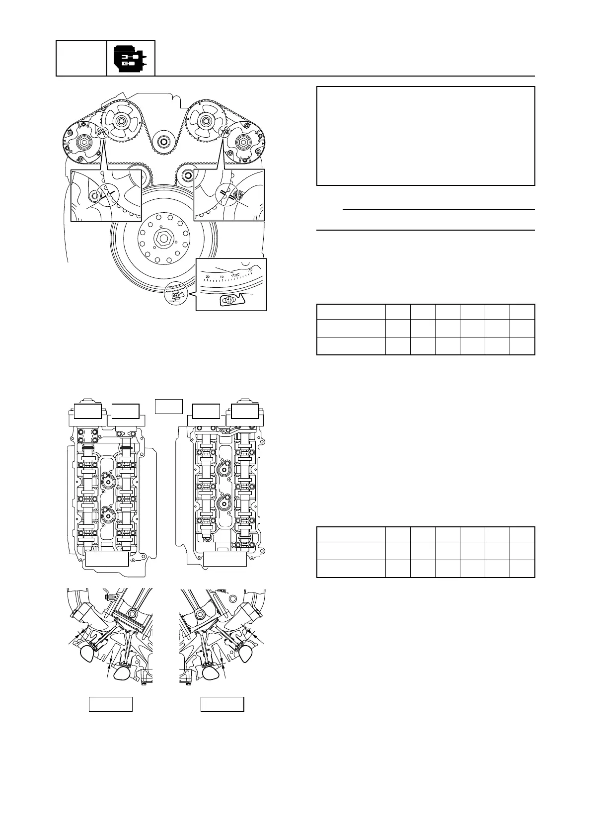
12. Remove the cylinder head covers.
13. Measure the valve clearances f and g
according to steps 14–16.
TIP:
Write down the measurement data.
14. Measure the intake and exhaust valve
clearances of the specified cylinders.
Adjust if out of specification. See “Adjust-
ing the valve clearance” (7-4).
—: Not applicable
: Specified cylinder
15. Turn the flywheel magnet an additional
360° clockwise and align the “1TDC”
mark b on the flywheel magnet with the
pointer c.
16. Measure the intake and exhaust valve
clearances of the specified cylinders.
Adjust if out of specification. See “Adjust-
ing the valve clearance” (7-4).
—: Not applicable
: Specified cylinder
17. Install the cylinder head covers. See
“Installing the cylinder head cover” (7-
44).
18. Install the engine ECM bracket 2.
19. Fasten the knock sensor lead a using
the holder 3 on the engine ECM
bracket.
20. Connect the water cooling hose 1.
b
c
e
d
#1
#3
#5
#2
#4
#6
PORT STBD
UP
EX INEXIN
f
g
PORT
f
g
STBD
Valve clearance (cold):
Intake f:
0.205 ± 0.035 mm (0.0081 ± 0.0014
in)
Exhaust g:
0.345 ± 0.035 mm (0.0136 ± 0.0014
in)
#1 #2 #3 #4 #5 #6
IN —
——
EX ———
#1 #2 #3 #4 #5 #6
IN
———
EX
———