5-54
5
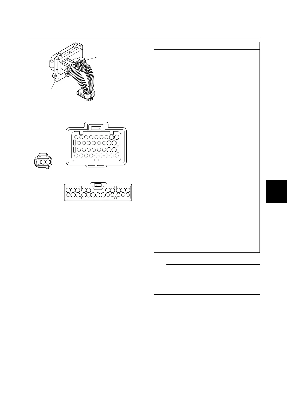
8. Check the wiring harness for continuity.
TIP:
Make sure that there is continuity between
terminal 3 of the ignition coil couplers a and
one of the terminals of the fuse holder cou-
pler c.
9. Connect the fuse holder coupler, and
then install the fuse holder.
10. Install the intake manifold (STBD). See
“Installing the intake manifold” (6-18).
11. Connect the engine ECM coupler.
NOTICE: Make sure that the rubber
seal is installed properly in the engine
ECM coupler.
1
c
54 53
63 62
71 70
b
a
c
3 2 1
9
10
22 21 20 19 18 17 16
8 7 6 5 4 3 2 1
Wiring harness continuity:
Ignition coil #1
a Terminal 1–b Terminal 71
a Terminal 2–Ground
a Terminal 3–
c Terminals 1–10 and 16–22
Ignition coil #2
a Terminal 1–b Terminal 70
a Terminal 2–Ground
a Terminal 3–
c Terminals 1–10 and 16–22
Ignition coil #3
a Terminal 1–b Terminal 63
a Terminal 2–Ground
a Terminal 3–
c Terminals 1–10 and 16–22
Ignition coil #4
a Terminal 1–b Terminal 62
a Terminal 2–Ground
a Terminal 3–
c Terminals 1–10 and 16–22
Ignition coil #5
a Terminal 1–b Terminal 54
a Terminal 2–Ground
a Terminal 3–
c Terminals 1–10 and 16–22
Ignition coil #6
a Terminal 1–b Terminal 53
a Terminal 2–Ground
a Terminal 3–
c Terminals 1–10 and 16–22
Ignition unit and component


 To Next Page