5-62
5
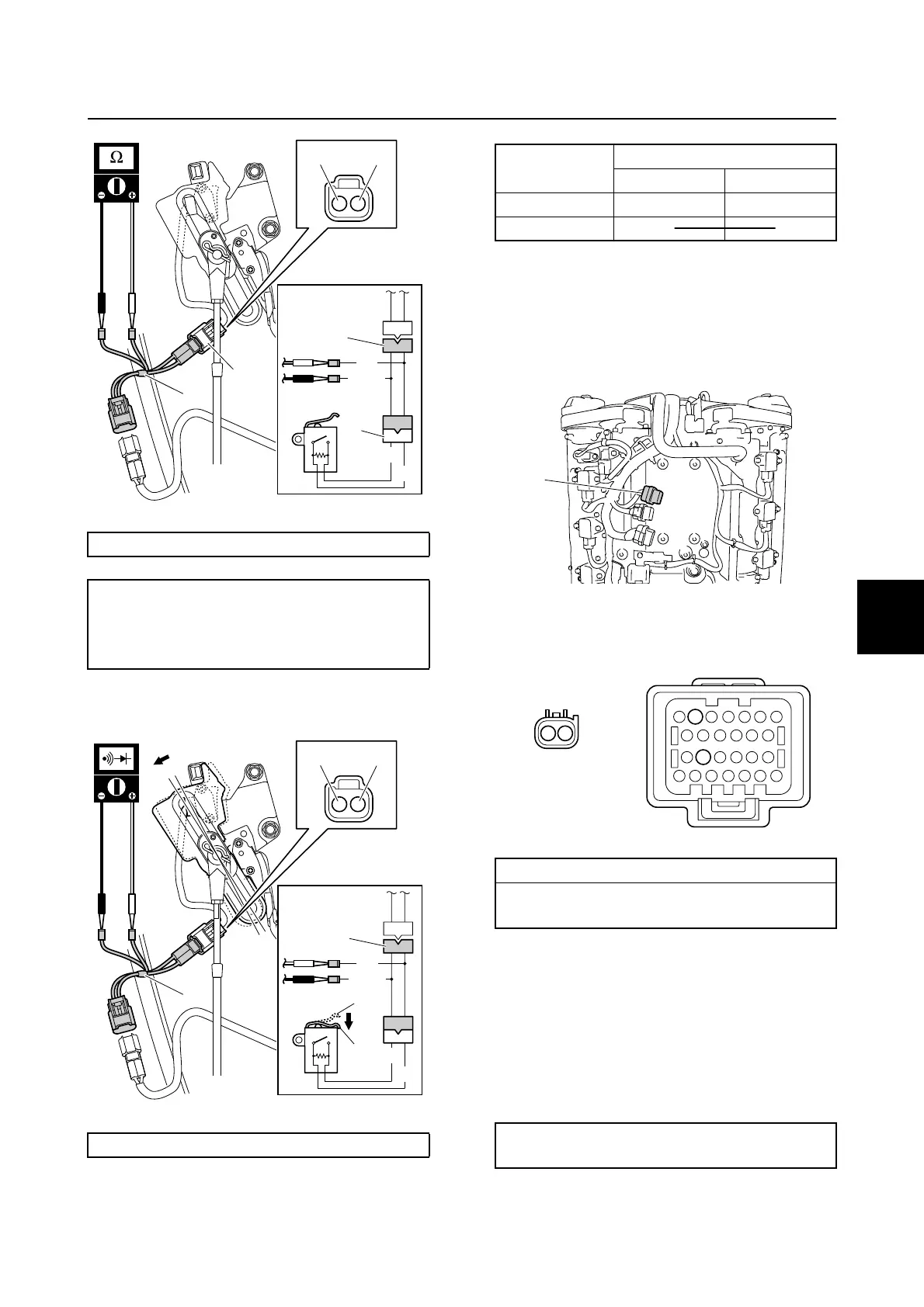
7. Check the shift cut switch for continuity.
Replace if out of specification.
8. Disconnect the special service tool.
9. Remove the engine ECM cover.
10. Remove the engine ECM, and then dis-
connect the engine ECM coupler e.
11. Check the wiring harness for continuity.
12. Connect the engine ECM coupler.
NOTICE: Make sure that the rubber
seal is installed properly in the engine
ECM coupler.
13. Install the engine ECM, and then tighten
the engine ECM bolts to the specified
torque.
14. Install the engine ECM cover.
Test harness (2 pins) 1: 90890-06867
Shift cut switch resistance (reference
data):
Blue/Yellow (L/Y)–Black (B)
4.5–4.9 kΩ
Test harness (2 pins) 1: 90890-06867
G/W
G
B
L/Y
1
b
b
BL/Y
1
G/W
G
B
L/Y
1
c
c
d
d
1
BL/Y
Switch
position
Lead color
L/Y B
Free c
Pushed d C
CC
CC
CC
C
Wiring harness continuity:
a Terminal 1–e Terminal 18
a Terminal 2–e Terminal 6
Engine ECM bolt:
7 N·m (0.7 kgf·m, 5.2 ft·lb)
e
a
21
e
18
6
Ignition unit and component
 Loading...