7-5
POWR
Power unit
TIP:
Make sure to keep the parts in the order as
they were removed.
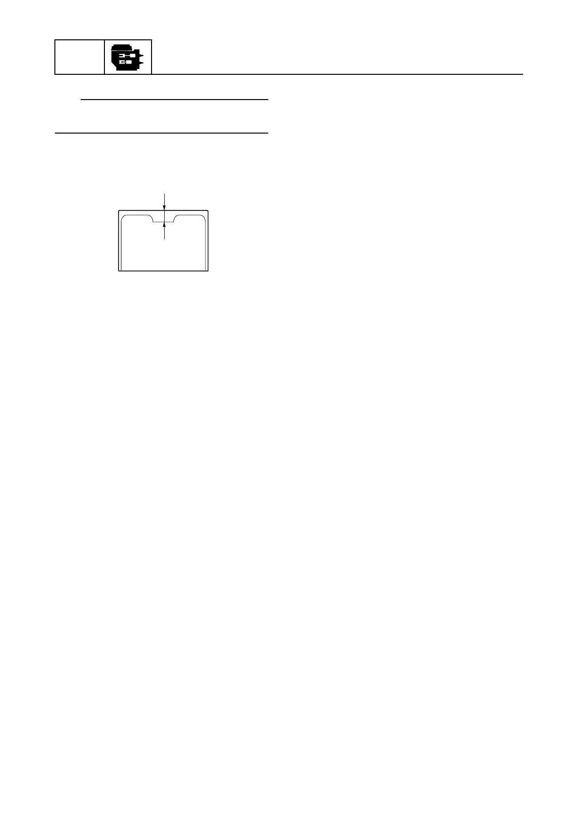
10. Measure the valve lifter thickness e, and
then write down the measurement data.
11. Select the necessary valve lifter by calcu-
lating its thickness using the following
formula.
Calculation formula:
Necessary valve lifter thickness =
Removed valve lifter thickness +
Measured valve clearance –
Specified valve clearance
Example:
Removed valve lifter thickness = 2.10 mm
Measured valve clearance = 0.30 mm
Specified valve clearance = 0.20 mm
Necessary valve lifter thickness
= 2.10 + 0.30 – 0.20
= 2.20 mm
12. Install the necessary valve lifter into the
cylinder head.
13. Install the camshafts, driven sprockets,
and VCT assemblies. See “Installing the
camshaft and driven sprocket” (7-50).
14. Install the timing belt. See steps 1–9 in
“Installing the timing belt” (7-39).
15. Install the stator assembly and flywheel
magnet. See steps 1–7 in “Installing the
flywheel magnet” (7-17).
16. Measure the valve clearances. See steps
14–16 in “Checking the valve clearance”
(7-2).
17. Install the intake manifolds. See in
“Installing the intake manifold” (6-18).
18. Check the pulser coil air gap. See steps
2–5 in “Checking the pulser coil air gap”
(7-1).
19. Install the wiring harness guide and wir-
ing harness. See steps 13 and 14 in
“Installing the wiring harness” (7-23).
20. Install the fuel hoses and fuel rail covers.
21. Connect the quick connectors. See “Con-
necting the quick connector” (6-8).
e