7-26
7
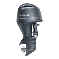
TIP:
Make sure to install the holder e and plastic
ties N in the order 1, 2, and so on.
29. Install the water pressure sensor coupler
G to the bracket.
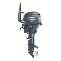
30. Connect the cam position sensor coupler
(STBD IN) H and ignition coil couplers
(STBD) J.
31. Install joint coupler 1 L to the wiring har-
ness guide.
32. Install the air-fuel sensor coupler M to
the bracket.
33. Install joint coupler 2 N to the bracket.
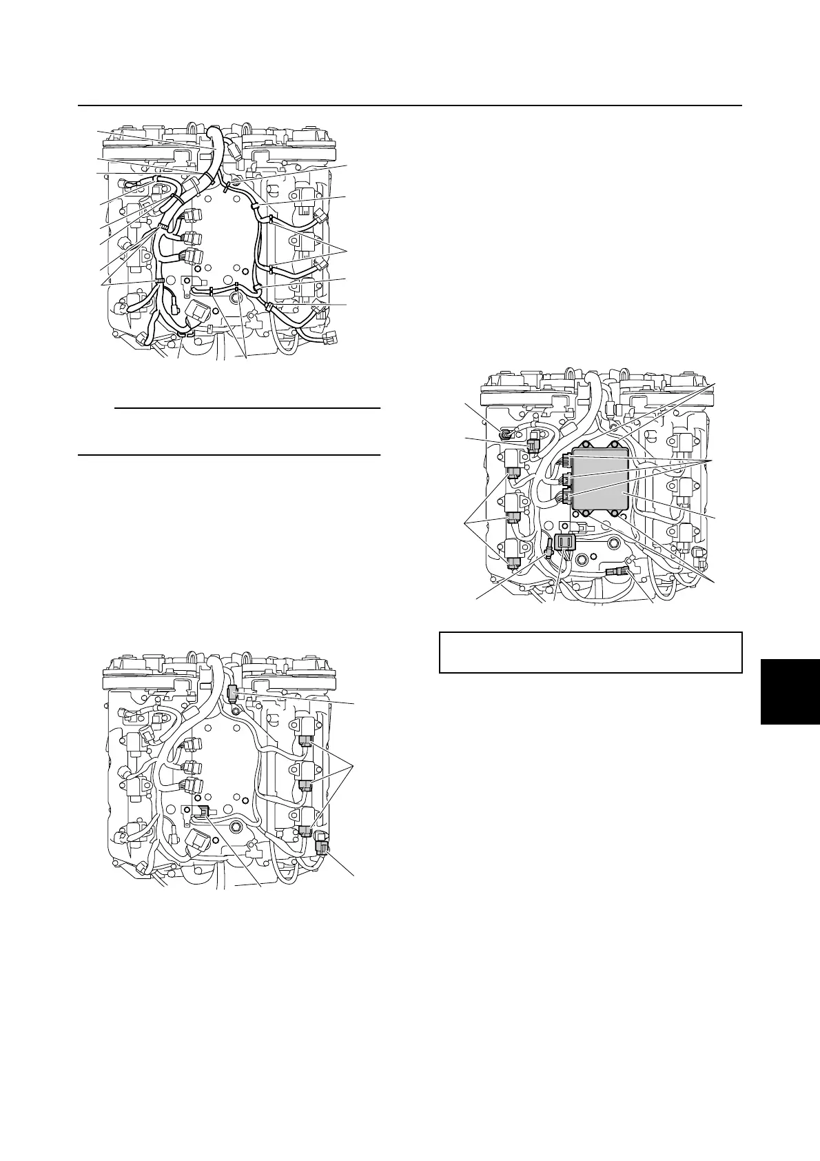
34. Connect the knock sensor coupler R,
and then install the knock sensor coupler
to the engine ECM bracket.
35. Connect the ignition coil couplers
(PORT) T, cam position sensor coupler
(PORT EX) U, and cam position sensor
coupler (PORT IN) Y.
36. Connect the engine ECM couplers Z.
NOTICE: Make sure that the rubber
seal is installed properly in each
engine ECM coupler.
37. Install the engine ECM P, and then
tighten the engine ECM bolts Q to the
specified torque.
38. Install the fuel hoses and fuel rail covers.
See steps 7 and 9 in “Installing the fuel
injector” (6-46).
39. Connect the quick connectors. See “Con-
necting the quick connector” (6-8).
40. Install the intake manifold (PORT). See
“Installing the intake manifold” (6-18).
41. Install the intake silencer, and then con-
nect the air temperature sensor coupler
and blowby hose. See “Installing the
intake silencer” (6-19).
L
K
K
KM
1
5
O
N
N
e
e
e
3
2
G
J
L
H
Engine ECM bolt Q:
7 N·m (0.7 kgf·m, 5.2 ft·lb)
Y
U
T
R
N
M
P
Q
Z
Q
Wiring harness
 Loading...