GEQ function
156 PM5D/PM5D-RH Owner’s Manual Reference section
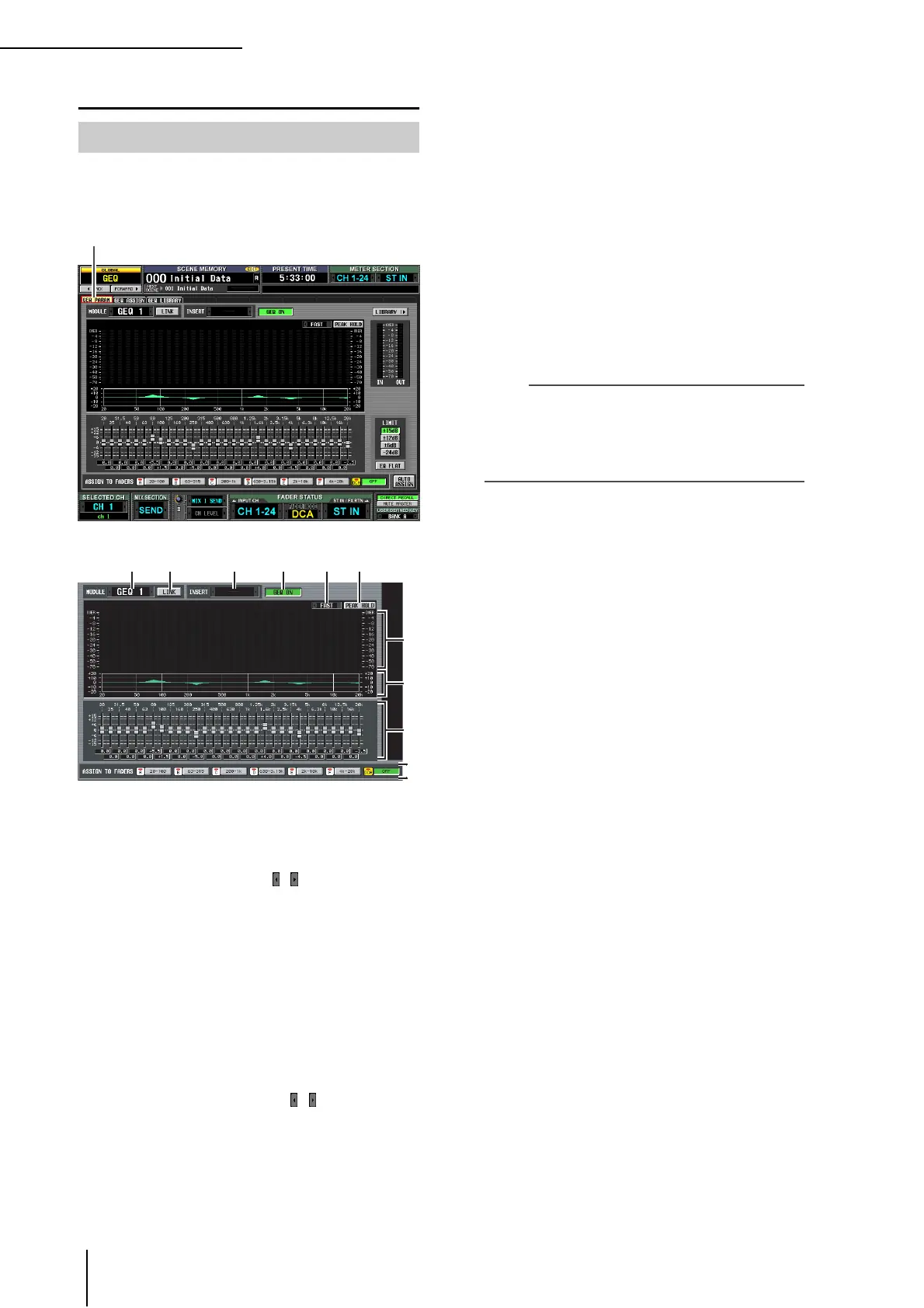
GEQ function
Here you can adjust the boost/cut for a 31-band graphic
EQ, specify the input/output patching, and assign a GEQ
to faders.
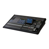
A Module select
Of the twelve graphic EQ modules (GEQ1–GEQ12),
select the module that you want to operate. To switch
between modules, place the cursor here and turn the
[DATA] encoder, or click the / buttons at left or
right.
B LINK button
This button links adjacent odd-numbered → even-
numbered graphic EQ modules. When you turn this
button on, a window will appear, allowing you to select
whether the parameters will be copied from one mod-
ule to the other, or whether both modules will be
initialized.
C INSERT (Insert destination)
Selects the location at which the graphic EQ module
will be inserted. Move the cursor to this box and turn
the [DATA] encoder or click the / buttons at left or
right to display the desired insertion destination, and
then press the [ENTER] key to finalize the change.
You can choose the following insertion destinations.
• INS CH1–INS CH48
Input channel 1–48 insert in/out
• INS STIN1 (L/R)–INS STIN4 (L/R)
ST IN channel 1–4 (L/R) insert in/out
• INS MIX1–INS MIX24
MIX channel 1–24 insert in/out
• INS MTRX1–INS MTRX8
MATRIX channel 1–8 insert in/out
• INS ST A (L/R)
STEREO A channel (L/R) insert in/out
• INS ST B (L/R)
STEREO B channel (L/R) insert in/out
• INS MON (L/R/C)
MONITOR channel (L/R/C) insert in/out
Note
• When you select the insertion destination here, insert in/out
will be patched simultaneously, and insertion will automati-
cally be turned on for the channel into which the graphic EQ
module was inserted.
• If you move the cursor away without pressing the [ENTER]
key, the setting will revert to its original state.
D GEQ ON/OFF button
Switches the currently selected graphic EQ module on/
off.
E SLOW/FAST
Switches the fall speed of the spectrum analyzer
between slow or fast. This setting does not affect the
meters in other screens or the meters on the panel.
F PEAK HOLD
Switches the peak hold function on/off for the spec-
trum analyzer. The peak level for each band is held
while this button is on. (To reset the peak level display,
turn this button off and then on again). This setting
does not affect the meters in other screens or the
meters on the panel.
G Spectrum analyzer
This is an analyzer that shows a realtime level display
for each band of the input signal.
H EQ graph
Indicates the current frequency response of the graphic
EQ.
I Faders
These faders cut/boost the frequency bands of the
graphic EQ. The actual values are shown in the numer-
ical boxes below.
J ASSIGN TO FADERS
These buttons divide the 31 bands of the graphic EQ
into six groups so that you can use the DCA faders to
adjust the boost/cut amount of each band. Click one of
the six buttons A (20.0-100), B (63.0-315), C (200-
1.00k), D (630-3.15k), E (2.00k-10.0k), F (4.00k-
20.0k). DCA faders 1–8 will be assigned to the corre-
sponding region of frequency bands, allowing you to
control them with the DCA faders. At this time, the
divisions of the corresponding faders and the value in
the numerical box screen will turn red in the screen. To
return to the original state, press the DCA (OFF) but-
ton in the screen or the [DCA] button on the panel.
GEQ PARAM (GEQ parameter) screen
GEQ PARAM
J
7
8
9