MATRIX/ST function
242 PM5D/PM5D-RH Owner’s Manual Reference section
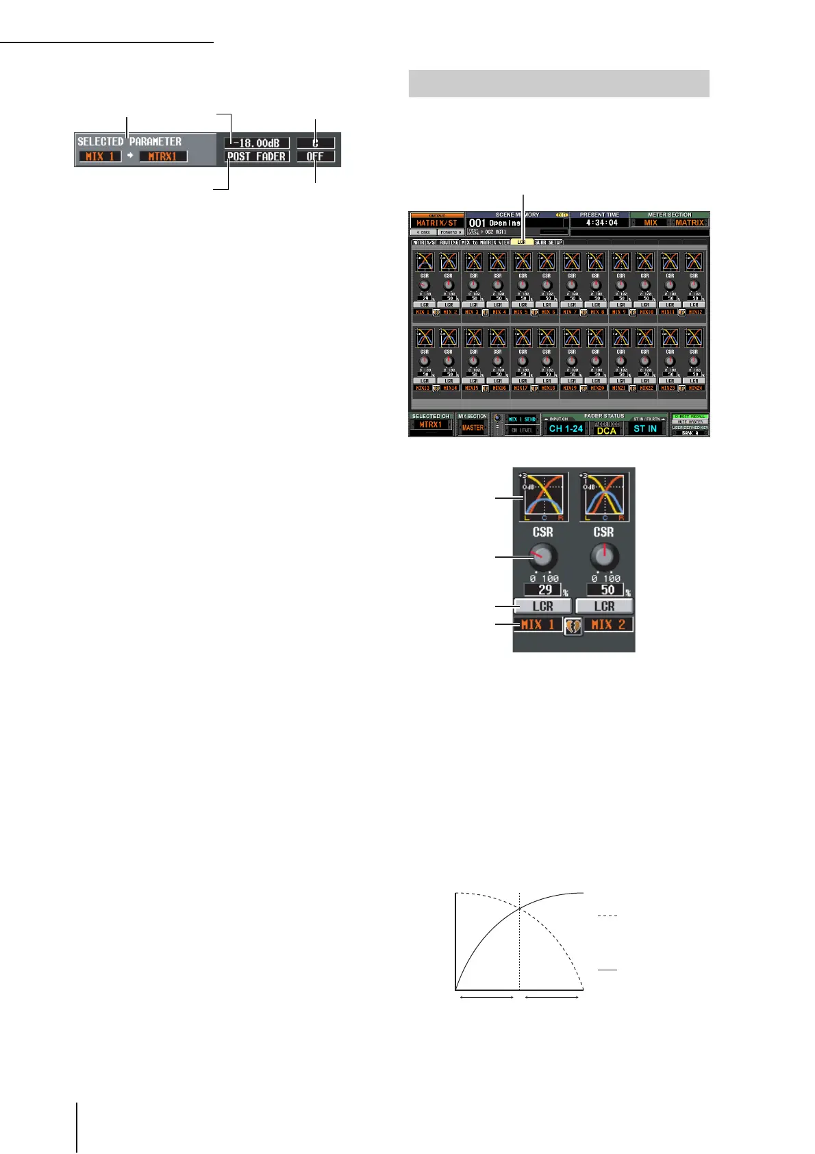
D SELECTED PARAMETER (currently selected
parameter)
This area indicates the channel (MIX or STEREO A/B)
and MATRIX bus corresponding to the grid where the
cursor is currently located. The four boxes at right
indicate the values for the grid where the cursor is cur-
rently located.
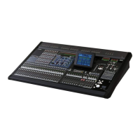
Here you can make settings for LCR mode, which allows
three-channel playback by adding a CENTER channel to
the L/R channels of the STEREO bus. This function can be
used only with MIX channels.
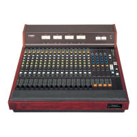
A Response graph
These graphs indicate the approximate LCR response
for each MIX channel. The graph will change as the
CSR knob (
2) is edited.
B CSR (Center Side Ratio)
This knob adjusts the proportional level of the CEN-
TER channel relative to the L/R channels. The range is
0–100%.
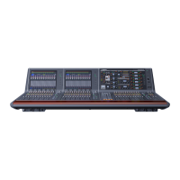
If the CSR knob is set to 0%, turning the PAN knob in
the MIX TO STEREO area of the MATRIX/ST ROUT-
ING screen (or the [PAN] encoder in the SELECTED
CHANNEL section) will change the signal levels of the
L/R channels as shown below.
In this case, MIX TO STEREO PAN will operate as a
conventional PAN control, and no signal will be sent to
the CENTER channel.
Send level
an
sp
aye
e
es
na-
tion MATRIX channel is
paired and an odd-numbered
MATRIX bus is selected)
Position from which
the signal is sent
On/off switch for the signal
sent to the MATRIX bus
LCR screen
LCR
4
3
1
2
CRL
Signal sent to the
R channel
[PAN] encoder
Signal sent to the
L channel
Signal level