PM5D/PM5D-RH Owner’s Manual Reference section 247
Information shown
in the display
Function
menu
Global
functions
Output
functions
Input
functions
Appendices
O Fader
This controls the output level of the channel.
P CUE
This button cue-monitors the signal of the channel.
This is linked with the [CUE] key of the corresponding
channel.
Q ON/OFF (Channel on/off)
This is an on/off switch for the signal that is output
from the channel. This is linked with the [ON] key of
that channel.
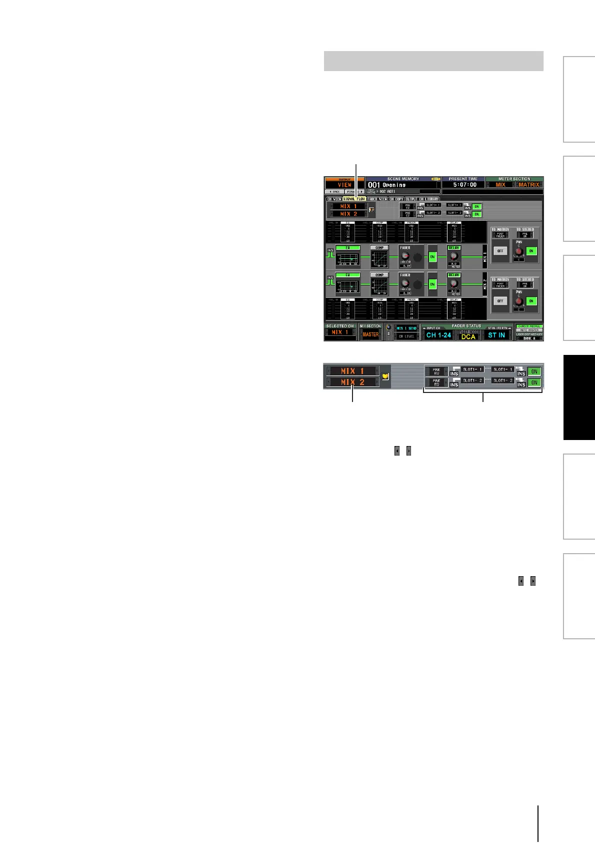
This screen shows the signal flow for adjacent odd-num-
bered/even-numbered MIX/MATRIX channels or for
STEREO A/B channels. In this screen you can also edit
some of the parameters, and access other screens. You can
also determine the location within the signal flow at which
clipping occurred.
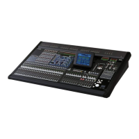
A Channels
These are the numbers of the channels you are editing.
By clicking the / buttons at left and right, you can
switch the display in units of two channels.
If the corresponding MIX/MATRIX channels are
paired (or if a STEREO A/B channel is selected), a heart
symbol is displayed at the right. You can click this sym-
bol to enable/disable pairing for the MIX/MATRIX
channels.
B Insert
This area displays insert-related information for the
two selected channels (insert point, the ports patched
to insert in/out, and insert on/off status).
Here you can also select the insert point (use the /
buttons at left and right), or switch insertion on/off
(use the ON/OFF button).
SIGNAL FLOW screen