OUTPUT VIEW function
246 PM5D/PM5D-RH Owner’s Manual Reference section
If you click the mini-graph, the EQ PARAM screen for
that channel will appear.
C Compressor
This area shows the amount of gain reduction and the
output level of the compressor, a mini-graph showing
the approximate response of the compressor, and the
compressor on/off status. You can click the COMP
ON/OFF button to switch the compressor on/off in
this screen. If you click the mini-graph, the COMP
PARAM screen for that channel will appear.
D Insert in
This area indicates the insert point, the insert on/off
status, and the type and input level of the port that is
patched to insert-in. You can click the INSERT ON/
OFF button to switch insertion on/off in this screen.
If an internal effect is patched, the effect type and
BYPASS button are displayed. If a GEQ module is
patched, the GEQ ON/OFF button and a mini-graph
showing the GEQ response are displayed.
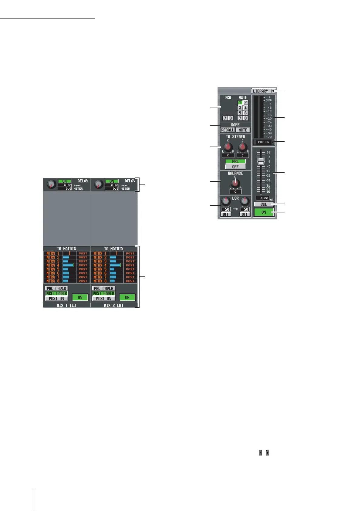
E DELAY
In this area you can view and edit the delay time of the
internal delay and its on/off status.
F TO MATRIX (only for MIX channels and
STEREO A/B channels)
This area shows the send level, send position, and on/
off status of the signals sent from the corresponding
MIX channel or STEREO A/B channel to MATRIX
buses 1–8. You can also edit the send level, send posi-
tion, and on/off status in this screen. Here’s how to do
this.
• To edit the send level of signals sent to the MATRIX
bus
Move the cursor to the desired bar graph in the list,
and turn the [DATA] encoder.
• To edit the send position of signals sent to the
MATRIX bus
Click either the PRE FADER, the POST FADER, or the
POST ON button located below.
Alternatively, you can edit the setting by moving the
cursor to the PRE or POST indication in the list and
pressing the [ENTER] key or turning the [DATA]
encoder.
• To switch the signal sent to the MATRIX bus on/off
Click the ON/OFF button located below.
You can also switch this on/off by moving the cursor to
a bar graph in the list and pressing the [ENTER] key.
The bar graph is colored blue when on, and gray when
off.
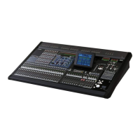
G DCA group / Mute group
Here you can assign or cancel DCA group and MUTE
group assignments.
H RECALL SAFE / MUTE SAFE
Here you can enable or disable Recall Safe and Mute
Safe settings.
I TO STEREO (MIX channels only)
Here you can switch the signal sent from a MIX chan-
nel to the STEREO bus on/off, and edit its panning and
send position (pre-on / post-on) (➥ p.239).
J BALANCE (only for paired MIX/MATRIX
channels and STEREO A/B channels)
This adjusts the left/right volume balance of the signals
output from paired MIX channels or STEREO A/B
channels.
K LCR (MIX channels only)
Here you can switch LCR mode on/off, and adjust CSR
(the level of the CENTER channel relative to the L/R
channels) (➥ p.242).
L LIBRARY
This button accesses the OUTPUT CH LIBRARY
screen (➥ p.251), where you can store/recall library
settings for output channels.
M Level meter
This level meter indicates the output level of the
channel.
N Signal detection point
This is the point at which the signal level shown in the
level meter (
M) is detected (PRE EQ, PRE FADER,
POST FADER, POST DELAY, or POST ON). You can
edit this setting by clicking the / buttons at the left
and right.
5
6
7
L
M
O
N
P
Q
8
9
J
K