OUTPUT VIEW function
248 PM5D/PM5D-RH Owner’s Manual Reference section
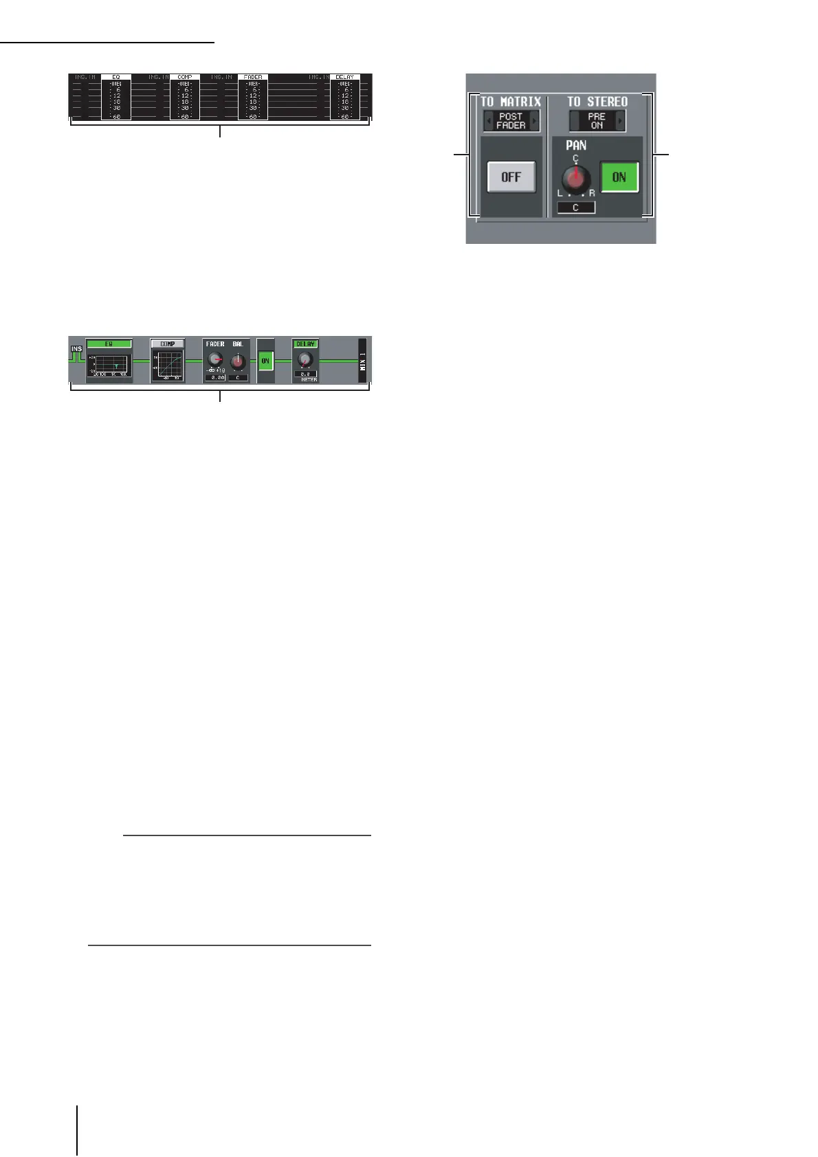
C Level meters
These meters indicate the levels within the signal flow.
Levels are detected at the following locations.
• EQ (immediately before and after the EQ)
• COMP (immediately before and after the
compressor)
• FADER (immediately before and after the fader)
• DELAY (immediately before and after the delay)
• INSERT IN (immediately after the insert point)
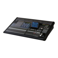
D Signal flow
This area indicates the signal flow of the selected chan-
nel. The following parameters are displayed.
• EQ (Equalizer)
This indicates the EQ on/off status and the approxi-
mate response curve. You can click the EQ button to
switch EQ on/off, or click the mini-graph to access the
EQ PARAM screen for the corresponding channel.
• COMP (Compressor)
This indicates the compressor on/off status and the
approximate response curve. You can click the COMP
button to switch the compressor on/off, or click the
mini-graph to access the COMP PARAM screen for the
corresponding channel.
• FADER
This indicates the output level of the channel. This is
linked with the encoder or fader of the corresponding
channel.
• ON/OFF (On/off)
Turns the channel on/off. This is linked with the [ON]
key of the corresponding channel.
• DELAY
Here you can switch the internal delay on/off and edit
the delay time.
Hint
• If insert is enabled, the currently selected insert point is
shown in this signal flow.
• If the signal clips, the signal flow (horizontal line) after clip-
ping is displayed in red. If an output is turned off so that the
signal does not flow any further, the subsequent flow is dis-
played in gray. If PEAK HOLD is on, the flow indication will
stay red if clipping occurs even once, making it easier to see
that clipping has occurred.
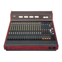
E TO MATRIX (only for MIX channels and
STEREO A/B channels)
This area shows the on/off status of the signal sent
from the MIX channel or STEREO A/B channel to the
MATRIX buses, and the point from which the signal is
sent.
F TO STEREO (MIX channels only)
This area shows the pan, the send position, and the on/
off status of the signal sent from the MIX channel to
the STEREO bus.
65