PM5D/PM5D-RH Owner’s Manual Reference section 185
Information shown
in the display
Function
menu
Global
functions
Output
functions
Input
functions
Appendices
7
If you want scene changes on the PM5D to be
linked with scene changes on the DME series
unit, turn on the MIDI PGM CHANGE button
in the center of the screen.
If the MIDI PGM CHANGE button is on, switching
the scene on the PM5D will cause a program change
message of a number corresponding to that scene to be
sent to the DME.
Hint
• The above program change message is always transmitted
via the MY16-C card or the CASCADE IN/OUT connector.
This is not affected by MIDI PGM CHANGE or by the MIDI
program change transmission port or transmission on/off
setting selected in the MIDI SETUP screen.
• The program number assignment for each scene can be
specified in the MIDI PGM CHANGE screen.
8
To initiate communication between the PM5D
and the DME series unit, click the CONNECT
button to turn it on.
While the CONNECT button is on, parameter opera-
tions and scene store/recall operations on the DME can
be remotely controlled from the PM5D. To terminate
communication, click the CONNECT button once
again to turn it off.
❏ Controlling DME parameters
Here’s how the parameters of the DME series unit can be
controlled from the PM5D. If desired, the changes you
make can be saved in the scene of the DME series unit.
1
In the DME CONTROL screen, choose SETUP,
and turn on the CONNECT button to initiate
communication.
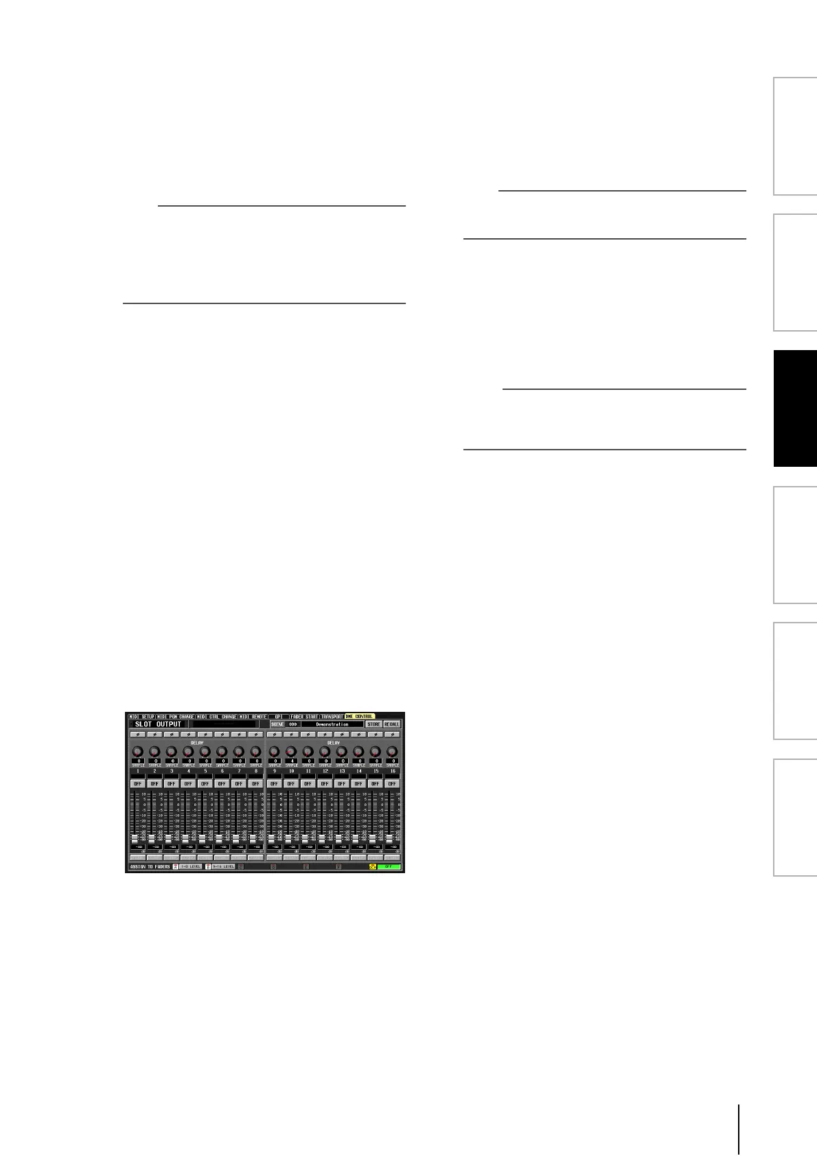
2
In the upper left of the screen, use the compo-
nent type / component selection areas to
select the component you want to control.
If a component other than SETUP is selected, internal
parameters of the DME can be controlled from the
PM5D screen. The following illustration is an example
of when the SLOT OUTPUT component is selected.
3
Use the knobs, sliders, and buttons in the
screen to control the parameters of the DME
series unit.
Knob, slider, and button operation methods are the
same as for the PM5D’s internal parameters. For details
on the parameters that can be operated for each com-
ponent, refer to the owner’s manual of the DME series
unit.
4
If you want to use DCA faders 1–8 to control
the parameters of the component, click an A–F
button in the ASSIGN TO FADERS area.
When you click a button A–F, the corresponding
parameters will be assigned to DCA faders 1–8, and can
be controlled by the faders. To return to the previous
state, click the DCA button.
Hint
As an alternative to clicking the A–F buttons, you can obtain
the same result by holding down the top panel [SHIFT] key
and pressing the [A]–[F] keys of the FADER MODE section.
5
If you want to store your changes in a scene of
the DME series unit, use the SCENE field in the
upper right of the screen to select the store-
destination, and click the STORE button.
The edited settings will be stored as a scene in the
DME. To recall this scene, use the SCENE field in the
upper right of the screen to select the scene, and click
the RECALL button.
Note
When storing a DME scene from the PM5D’s screen, you can
only store by overwriting an existing scene on the DME; you
cannot store the settings as a new scene or edit the scene
name.