MON/CUE function
214 PM5D/PM5D-RH Owner’s Manual Reference section
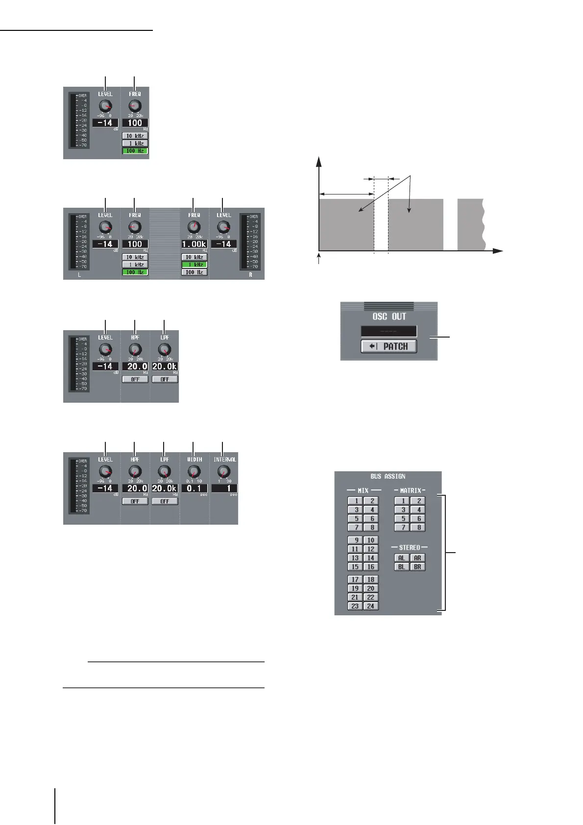
• If SINE WAVE 1CH is selected
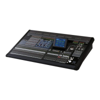
• If SINE WAVE 2CH is selected
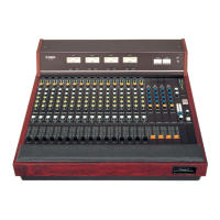
• If PINK NOISE is selected
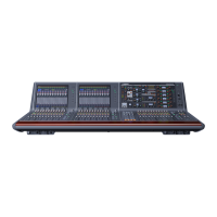
• If BURST NOISE is selected
D LEVEL
This knob adjusts the output level of the oscillator. The
range is –96 dB to 0 dB. The level meter beside the
knob indicates the output level.
E FREQ (Frequency)
This knob specifies the frequency of the sine wave pro-
duced by the oscillator. The range is 20 Hz–20 kHz (the
current setting is shown in the numerical box below).
You can use the 10 kHz /1 kHz / 100 Hz buttons to
select a preset frequency.
Hint
If SINE WAVE 2CH is selected, you can specify the level and
frequency of each channel independently.
F HPF (High Pass Filter)
G LPF (Low Pass Filter)
Here you can make settings for the HPF/LPF through
which the pink noise or burst noise is sent. The knob
above sets the cutoff frequency (20 Hz–20 kHz), and
the button below switches the filter on/off.
H WIDTH
I INTERVAL
If burst noise is selected, these knobs select the dura-
tion of the noise itself (WIDTH) and the duration of
silence between noise bursts (INTERVAL).
The range is 0.1–10 sec for WIDTH, and 1–30 sec for
INTERVAL. (The current setting is shown in the box
below each knob.)
J OSC OUT (Oscillator direct output)
This indicates the channel of the output jack / slot that
directly outputs the oscillator signal. If you want to
change the output destination, click the PATCH but-
ton to access the OUTPUT PATCH screen.
If SINE WAVE 2CH is selected, the L channel of the
oscillator is sent to the oscillator direct output.
K BUS ASSIGN
Here you can select the bus(es) or output jack(s) from
which the sine wave or noise will be sent. (Multiple
selections are allowed.)
MIX 1–24 . . . . . . . . MIX bus 1–24
MATRIX 1–8. . . . . . MATRIX bus 1–8
AL/AR . . . . . . . . . . . STEREO A bus L/R channels
BL/BR . . . . . . . . . . . STEREO B bus L/R channels
If SINE WAVE 2CH is selected, the L channel of the
oscillator is output to the odd-numbered bus or the L
jack, and the R channel of the oscillator is output to the
even-numbered bus or the R jack.
INTERVAL
WIDTH
Level
Time
Pink noise output
The BURST NOISE button is on
J
K