PAN/ROUTING function
284 PM5D/PM5D-RH Owner’s Manual Reference section
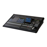
❏ If Surround Mode = 6.1ch
An F knob for controlling the front divergence and an
R knob for controlling the rear divergence are dis-
played. Use these two knobs to specify the proportion
(0–100) at which a signal positioned in the center will
be sent to the center buses (C, S, Bs) and the left/right
buses (L, R, Ls, Rs).
In 6.1ch mode, a LINK button
that links the front and rear diver-
gence is displayed between the F
knob and R knob. When you turn
the LINK button on, the F knob
value will be copied to the R knob,
and the F knob and R knob values
will be linked.
C LFE (Low Frequency Effect)
This adjusts the output level of the signal sent from the
input channel to the LFE (Low Frequency Effect) bus
for a subwoofer. You can use the ON/OFF button to
switch the signal sent from the input channel to the
LFE bus on/off.
The LFE knob and ON/OFF button are displayed only
when the surround mode is 5.1ch or 6.1ch.
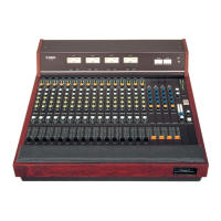
D Surround pan grid
This grid lets you control the surround panning, with
the listening point at the center. The current setting is
indicated by a O symbol.
E Position buttons
These buttons correspond to each surround bus. When
you click a button, the surround panning will move to
that position.
F SURROUND BUS ON/OFF buttons
These buttons are on/off switches for the signal sent
from the input channel to the corresponding surround
bus.
G Surround pan position
This indicates the coordinate locations of the O sym-
bol in the left/right direction and the front/rear
direction.
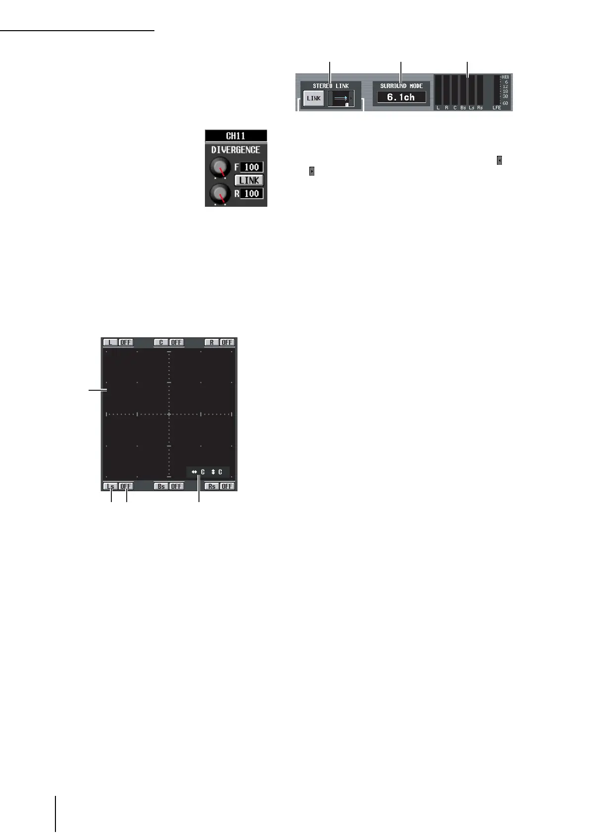
H STEREO LINK
This specifies whether sound image movement will be
linked between the two channels shown in the screen.
To link the movement of the two channels, use the /
buttons at left and right to select one of the eight link
patterns. (For details on how each pattern will operate,
refer to p.136)
I SURROUND MODE
This indicates the currently selected surround mode.
J Level meters
These meters show the master levels of the surround
buses.
4
5 6 7