i
General Contents
Chapter 1 OVERVIEW........................................................................................................... 1-1
1-1 Features of the SRCP Series Controller...................................................................................1-2
1-2 Setting Up for Operation .......................................................................................................1-3
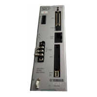
1-3 External View and Part Names ............................................................................................... 1-4
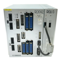
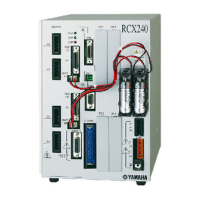
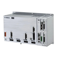
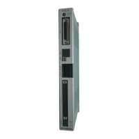
1-3-1 SRCP controller ............................................................................................................................................. 1-4
1-3-2 TPB ................................................................................................................................................................ 1-7
1-4 System Configuration .............................................................................................................1-8
1-4-1 System configuration ..................................................................................................................................... 1-8
1-5 Accessories and Options ........................................................................................................ 1-9
1-5-1 Accessories .................................................................................................................................................... 1-9
1-5-2 Peripheral options ......................................................................................................................................... 1-9
Chapter 2 INSTALLATION AND CONNECTION .................................................................. 2-1
2-1 Installing the SRCP Controller................................................................................................2-2
2-1-1 Installation method ....................................................................................................................................... 2-2
2-1-2 Installation location ....................................................................................................................................... 2-2
2-2 Connecting the Power Supply ................................................................................................2-3
2-2-1 Power supply ................................................................................................................................................. 2-3
2-2-2 Connecting the power supply ........................................................................................................................ 2-3
2-2-3 Installing an external leakage breaker ........................................................................................................... 2-4
2-2-4 Installing a circuit protector .......................................................................................................................... 2-4
2-2-5 Installing current control switches ................................................................................................................ 2-5
2-2-6 Insulation resistance and voltage breakdown tests ........................................................................................ 2-5
2-3 Grounding..............................................................................................................................2-5
2-4 Connecting the SRCP to the Control Unit ..............................................................................2-5
2-5 Connecting to the Robot ........................................................................................................ 2-6
2-5-1 Robot I/O connector and signal table ........................................................................................................... 2-6
2-5-2 Motor connector and signal table .................................................................................................................. 2-6
2-6 Connecting to the I/O. CN Connector ...................................................................................2-7
2-7 Connecting to the EXT. CN Connector ................................................................................... 2-8
2-8 Connecting to the Regenerative Unit .....................................................................................2-9
Chapter 3 I/O INTERFACE .................................................................................................... 3-1
3-1 I/O Signals .............................................................................................................................3-2
3-1-1 I/O. CN connector signals ............................................................................................................................. 3-2
3-1-2 EXT. CN connector signals ............................................................................................................................. 3-2
3-2 Input Signal Description ........................................................................................................3-3
3-2-1 Dedicated command input ............................................................................................................................ 3-3
3-2-2 General-purpose input (DI0 to DI7) .............................................................................................................. 3-6
3-2-3 SERVICE mode input (SVCE) .......................................................................................................................... 3-7
3-2-4 Interlock (LOCK) ........................................................................................................................................... 3-7
3-2-5 Emergency stop inputs 1, 2 (EMG1, EMG2) ................................................................................................... 3-7
3-3 Output Signal Description .....................................................................................................3-8
3-3-1 Dedicated output .......................................................................................................................................... 3-8
3-3-2 General-purpose output (DO0 to DO4) ........................................................................................................ 3-9
3-3-3 Feedback pulse output (PA±, PB±, PZ±, PZM±) ............................................................................................. 3-9
3-4 I/O Circuits ..........................................................................................................................3-10
3-4-1 I/O circuit specifications ............................................................................................................................. 3-10
3-4-2 I/O circuit and connection example ............................................................................................................ 3-11
3-5 I/O Connection Diagram .....................................................................................................3-12
3-5-1 Connection to PLC output unit .................................................................................................................... 3-12
3-5-2 Connection to PLC input unit ...................................................................................................................... 3-13
3-6 I/O Control Timing Charts ...................................................................................................3-14
3-6-1 When turning the power on ........................................................................................................................ 3-14
3-6-2 When executing a dedicated input command.............................................................................................. 3-15
3-6-3 When interlock signal is input ..................................................................................................................... 3-18
3-6-4 When emergency stop is input .................................................................................................................... 3-19
3-6-5 When alarm is issued ................................................................................................................................... 3-19
3-6-6 When executing a point movement command ............................................................................................ 3-20