3-8
A B
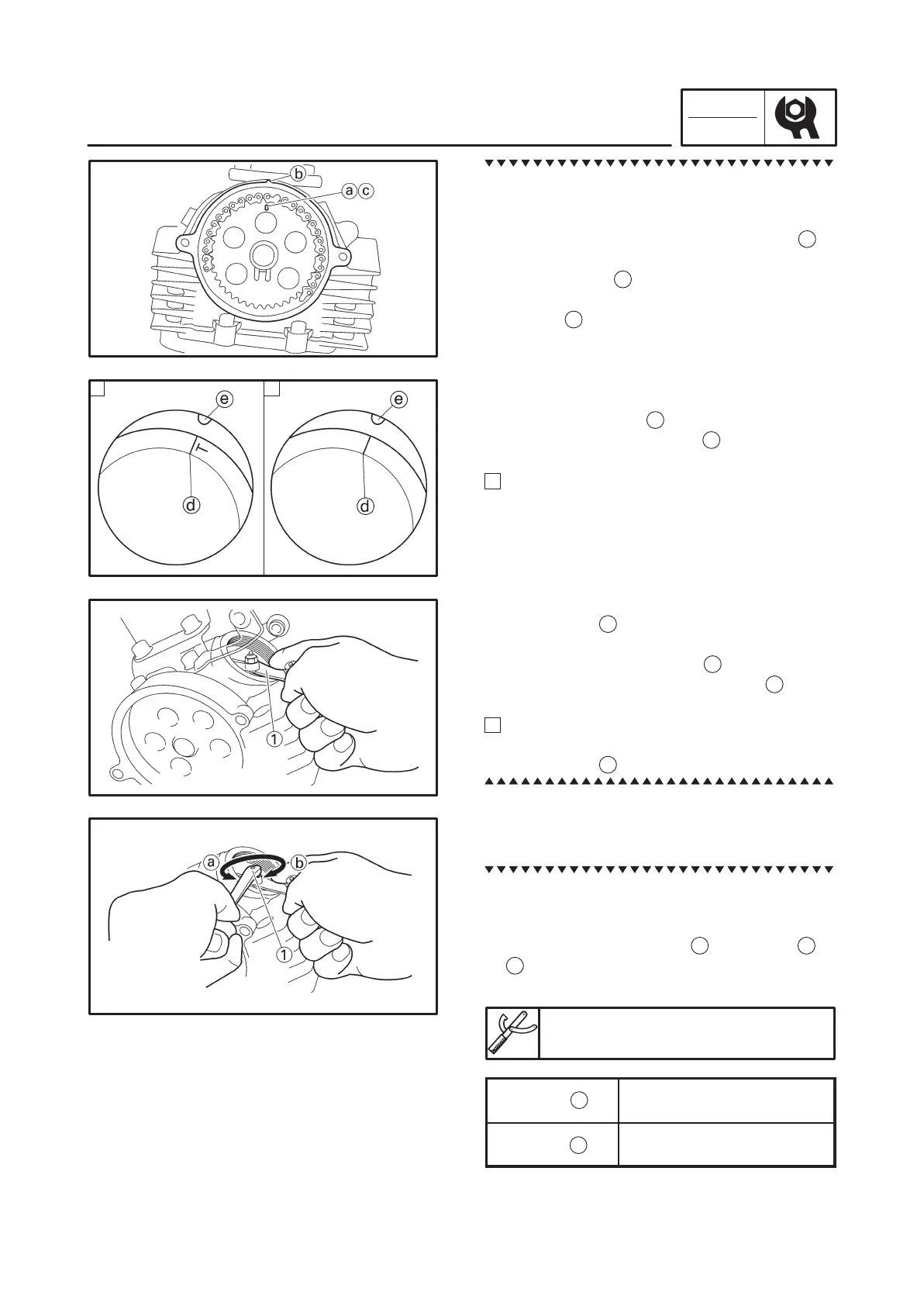
ADJUSTING THE VALVE CLEARANCE
CHK
ADJ
a
b
a. Turn the crankshaft counterclockwise.
b. When the piston is at TDC on the compres-
sion stroke, align either the alignment mark
in the camshaft sprocket (front cylinder)
a
or
alignment mark in the camshaft sprocket
(rear cylinder)
c
, dependant on which cylin-
der you are checking, with the stationary
pointer
b
on the cylinder head. When the
hole in the camshaft sprocket plate or punch
mark in the camshaft sprocket is aligned with
the stationary pointer, the piston is at top
dead center (TDC).
c. Align the “T” mark
d
on the generator rotor
with the stationary pointer
e
on the genera-
tor cover.
A
Front cylinder (“T” mark)
d. Measure the valve clearance with a thick-
ness gauge
1
.
e. Turn the crankshaft counterclockwise 300,
and then align the “I” mark
d
on the genera-
tor rotor with the stationary pointer
e
on the
generator cover.
B
Rear cylinder (“I” mark)
f. Measure the valve clearance with a thick-
ness gauge
1
.
10. Adjust
valve clearance
a. Loosen the locknut.
b. Insert a thickness gauge between the end of
the adjusting screw and the valve tip.
c. Turn the adjusting screw
1
in direction
a
or
b
until the specified valve clearance is ob-
tained.
Valve adjusting tool
90890-01311
Direction
Valve clearance is
decreased.
Direction
Valve clearance is
increased.
d. Hold the adjusting screw to prevent it from
moving and tighten the locknut to specifica-
tion.